Incline Impact Test: ASTM D880 Procedure, Equipment Setup, and Result Interpretation
Date: August 19, 2026 Categories: Technical Guides & Blog Views: 3719
An incline impact test reproduces the horizontal shocks that a loaded package or unit load can experience during handling and distribution. Under ASTM D880, Procedure A evaluates whether the container or shipping unit withstands impact, while Procedure B evaluates how well the packaging system protects its contents. A reliable result depends on more than releasing a carriage from a marked height: the laboratory must verify actual impact velocity, control specimen orientation, prevent unintended repeat impacts, inspect both package and product, and report the exact method used.
1. What the Test Simulates
2. Selecting the Right Impact Method
3. ASTM D880 Procedure A vs B
4. Standards and Test Programs
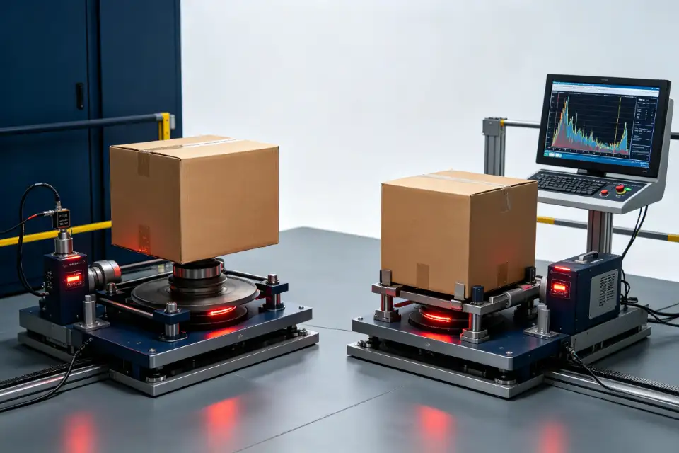
5. Apparatus and Setup
6. Laboratory Workflow
7. Velocity and Calibration
8. Results and Failure Modes
9. Common Errors
10. Equipment Selection
Frequently Asked Questions
What Does an Incline Impact Test Simulate?
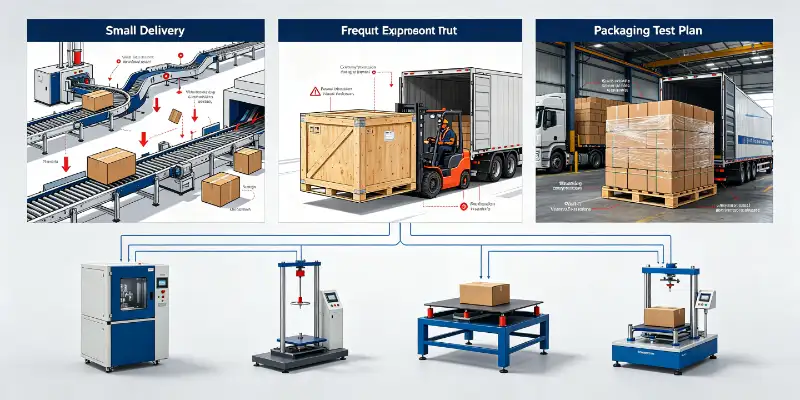
A package can survive stacking and vibration yet fail in one abrupt horizontal impact. A pallet load may strike a dock stop. A crate may be brought to a sudden halt during forklift handling. A package on a conveyor may collide with a fixed barrier or another load. These events load the side faces, closures, cushioning and product restraints in ways that a vertical drop does not reproduce.
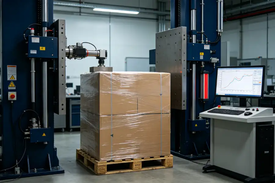
An incline impact tester creates a controlled version of that hazard. The specimen is placed on a carriage that travels toward a rigid impact surface. The package contacts the backstop at a specified velocity, allowing the laboratory to evaluate the response of the shipping unit and, where required, the protection provided to the product.
The purpose is not to recreate every detail of a distribution route. It is to create a repeatable shock that supports comparison, qualification or a defined distribution test program. ASTM notes that the method is useful for laboratory simulation of handling and transportation impacts, but also warns that differences in test machines—especially the impact surface—can limit correlation between laboratories. That warning should influence equipment specification, calibration and reporting.
The useful question is: did a correctly prepared package experience the required measured impact, in the required orientation, without an uncontrolled second event—and did it meet a pre-defined acceptance requirement?
Incline, Horizontal, Pendulum, or Free-Fall: Select the Hazard First
“Impact testing” is not one interchangeable procedure. Test direction, package size, handling mode and the selected standard determine which apparatus is appropriate. Using a convenient machine instead of the specified method can produce data that cannot support the intended claim.
| Method | Primary motion | Often considered when | Key control |
|---|---|---|---|
| Incline impact | Carriage descends an inclined track toward a backstop | Packages or unit loads require a controlled horizontal impact, especially where free-fall handling is impractical | Measured impact velocity and correct specimen contact |
| Horizontal impact | Powered carriage moves on a nominally horizontal path | A programmable or higher-energy horizontal event is required | Velocity profile, carriage control and backstop |
| Pendulum impact | Specimen or impact element follows a pendulum path | The authorized procedure permits that apparatus and the specimen can be safely restrained | Release geometry, velocity and contact alignment |
| Free-fall drop | Package falls vertically onto an impact surface | The hazard is a manual-handling drop and the package can be released in the required orientation | Drop height, orientation and clean release |
For an overview of vertical-impact equipment, see the drop tester types comparison. For a broader packaging sequence, the vibration versus drop testing guide explains why shock and vibration answer different questions.
ASTM D880 Procedure A vs Procedure B
ASTM D880 covers impact testing of loaded shipping containers and systems. The two procedures use similar impact principles but answer different qualification questions.
The choice changes specimen preparation and acceptance criteria. A substitute or dummy load may be useful in some comparative container work, while a protection assessment normally requires representative contents and the actual closing, sealing, strapping and internal restraint system. Do not decide after the impact which procedure the test “looks like.” Record the procedure, purpose and acceptance criteria before testing begins.
ASTM identifies the method as particularly suitable for large or heavily loaded containers, but it is not intended to represent every shock environment. If the distribution hazard involves rail-car coupling or another specialized event, confirm the appropriate method rather than extending D880 beyond its scope.
How ASTM D880, ISO 2244, and ISTA Programs Fit Together
A laboratory may encounter an ASTM method, an ISO method, an ISTA procedure, a carrier protocol, or a customer-specific test plan. These documents do not serve exactly the same role.
| Document | What it contributes | Planning implication |
|---|---|---|
| ASTM D880 | A method for impact testing loaded containers and shipping units, with Procedure A and B purposes | Control apparatus, specimen, measured impact and reporting to the selected procedure |
| ISO 2244 | Horizontal impact methods for complete, filled transport packages and unit loads, including horizontal or inclined-plane and pendulum approaches | Confirm the exact apparatus and sequence required by the current ISO edition |
| ISTA procedure | A distribution-test program that can combine conditioning, shock, vibration, compression and handling blocks | Select equipment from the exact procedure; incline impact is required, alternative or not applicable depending on the program |
The ISTA required-equipment matrix illustrates this difference: incline impact is required for some procedures and only an alternative or exception for others. ISO states that ISO 2244 can be used as a stand-alone horizontal-impact test or as one part of a distribution sequence.
Incline Impact Tester Components and Setup
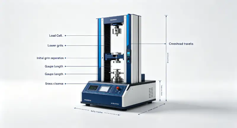
A useful purchase specification describes the test capability, not merely the track angle or maximum payload. Review the complete mechanical and measurement chain.
Track straightness, support, installation level and anchoring affect carriage travel and repeatability.
The platform must accommodate the specimen, rated load and required contact arrangement without uncontrolled movement.
The backstop must be large, rigid and aligned for the intended specimen faces and impact stress.
A repeatable release should not push, twist or pre-load the carriage.
The system must verify carriage speed immediately before impact over the required operating range.
A means of preventing or managing a second impact protects data quality and operator safety.
Restraint and friction must support correct travel while allowing the specified package-to-backstop event.
Guards, interlocks, emergency stops and a controlled operating zone should reflect the maximum moving mass and energy.
ASTM D880 describes gravity through a nominal incline, powered motion, and pendulum concepts within its apparatus provisions. Whatever the drive principle, calibration should demonstrate that the desired velocity can be achieved with a load that represents actual test conditions.
A Defensible Laboratory Workflow
The following workflow is a planning framework, not a replacement for the authorized standard or customer protocol. Values such as specimen conditioning, impact velocity, number of impacts and orientations must come from the selected document.
Identify whether the test evaluates container resistance, product protection, comparison between designs, or compliance with a distribution program. Agree on allowable package damage and product functionality before testing.
Record the standard, edition, procedure, sequence and customer modifications. Check that the laboratory owns or can access the authorized document.
Use the specified contents or justified equivalent load, actual internal packaging, production closures, sealing and straps. Condition the test unit where required.
Mark package members consistently and create an impact sequence sheet. This prevents an operator from testing the wrong face or repeating an orientation.
Inspect the track, carriage, release, impact surface, velocity sensor, rebound control and safety systems. Confirm current calibration or verification status.
Use preliminary loaded runs where permitted to establish the release setting. Do not assume that a historical carriage position produces the same speed for every load.
Place the specimen so the intended surface contacts correctly, clear the operating zone, release the carriage, record measured velocity and prevent an uncontrolled repeat impact.
Document package, closure, pallet, restraint, cushioning and product condition. Follow the program rules on whether inspection occurs after each impact or after the sequence.
Include specimen identity, test method, apparatus, velocity results, orientations, sequence, conditioning, deviations, damage observations, product checks and acceptance decision.
Impact Velocity: Calculate for Setup, Measure for Evidence
On an ideal incline, a theoretical speed can be estimated from the vertical drop of the carriage:
where v is theoretical velocity, g is gravitational acceleration, and h is vertical height change
This equation is useful for an initial setting, but a real machine is not frictionless. Wheel and bearing condition, track alignment, carriage mass, specimen position, restraint and air resistance affect actual velocity. The vertical height is also not simply the distance measured along the incline.
For test evidence, use the measured velocity immediately before impact and follow the tolerance and calibration provisions of the selected standard. ASTM calls for calibration with a load that simulates the package or product weight. This is why a machine specification should include an appropriate velocity-measurement system rather than relying only on release-height markings.
How to Interpret Damage and Decide Pass or Fail
A dent is not automatically a failure, and an intact outer box is not automatically a pass. Interpretation must follow the purpose of the test and the acceptance criteria agreed before testing.
| Area | Inspect for | Why it matters |
|---|---|---|
| Outer container | Panel buckling, split corners, puncture, seam opening and loss of shape | May reduce containment, stacking strength or handling safety |
| Closures and restraints | Tape or adhesive failure, staple pull-out, strap movement and fastener release | Can permit progressive opening or load shift later in distribution |
| Pallet or unit load | Deck damage, block movement, overhang, stretch-wrap loss and load displacement | Affects stability, forklift handling and subsequent test blocks |
| Interior packaging | Cushion crushing, insert movement, restraint release and product-to-box contact | Explains how shock reached the product even when the exterior appears acceptable |
| Product | Cosmetic damage, deformation, leakage, loose components and loss of function | Procedure B and customer protocols may require functional verification, not visual inspection alone |
Photograph the same views before and after testing and use a consistent damage scale. For comparative development, retain raw velocity and damage data for every design. For qualification, state the acceptance source—customer specification, carrier requirement, product standard or approved internal criterion.
Nine Errors That Make Incline Impact Data Unreliable
- Selecting the machine before the method. The laboratory later discovers that its package size, procedure or velocity range is unsupported.
- Using release position as the result. Actual speed changes with the loaded carriage and mechanical condition.
- Allowing the carriage to create the wrong contact. The intended package face should experience the specified event; an unintended carriage or restraint impact changes the load path.
- Ignoring a second impact. Rebound can add an uncontrolled shock that is not part of the planned procedure.
- Testing an unrepresentative pack. Different contents, cushioning, closures or straps can make a protection result meaningless.
- Changing orientation labels between operators. Face, edge and corner identification must remain consistent through the full sequence.
- Inspecting only the outer container. Product damage and internal movement may exist without obvious exterior failure.
- Comparing laboratories without apparatus details. Backstop, carriage and measurement differences can limit correlation.
- Reporting “ASTM/ISTA compliant” without detail. A reproducible report needs the exact standard edition, procedure, sequence, velocity, orientations and deviations.
Incline Impact Tester Selection Checklist
Send the equipment supplier a test envelope—not only a machine name. The information below allows the supplier to confirm capability and identify where a horizontal-impact system or another apparatus may be more appropriate.
Review the DERUI incline impact tester as a starting point, then send the actual test envelope for technical confirmation. Laboratories planning a broader capability can also review the packaging test lab guide and ISTA test equipment systems.
The right incline impact tester starts with your package and procedure—not a generic catalog specification.
Send DERUI the standard edition, package size and weight, target velocity, test frequency and reporting requirements for a technical configuration review.
Frequently Asked Questions
It is a controlled horizontal-shock test in which a loaded package or unit load travels on a carriage toward a rigid impact surface. The test evaluates container resistance, product protection, or a required distribution hazard.
Procedure A evaluates the ability of a container or shipping unit to withstand impacts. Procedure B evaluates the ability of the packaging system to protect its contents. Use the current authorized standard for complete requirements.
No. Incline impact applies a horizontal shock against a backstop, while a free-fall drop applies a mainly vertical impact onto a surface. Select the method that represents the governing standard and distribution hazard.
ASTM D880 includes shipping units such as pallet loads within its scope, subject to the selected procedure and apparatus capacity. Confirm package dimensions, mass, velocity, carriage and backstop requirements before testing.
Release position alone does not account for friction, load placement or machine condition. Measured velocity immediately before impact provides evidence that the required event occurred within the permitted tolerance.
Requirements vary by procedure. In the ISTA equipment matrix, incline impact may be required, an alternative, an exception or not applicable. Always check the exact current procedure rather than assuming one machine covers all ISTA tests.
Record the specimen, contents, package construction, conditioning, standard and procedure, apparatus, velocity results, impact sequence, orientations, damage observations, product checks, acceptance decision and all deviations.
- ASTM D880-92(2021), Standard Test Method for Impact Testing for Shipping Containers and Systems
- ISO 2244:2000, Packaging—Complete, filled transport packages and unit loads—Horizontal impact tests
- International Safe Transit Association, Required Equipment for ISTA Testing
This article is an engineering overview, not a reproduction of a standard. Purchase or access the authorized current document and follow its complete requirements.