ASTM D1922 vs ISO 6383-2: Film Tear Test Guide
Date: August 24, 2026 Categories: Technical Guides & Blog Views: 5790
ASTM D1922 and ISO 6383-2 use the same core Elmendorf principle and are identified by ASTM as technically equivalent. Both measure the force needed to propagate an already initiated tear through plastic film or non-rigid sheeting with a pendulum tester. Select the document named by the customer, then use its required specimen geometry, cutting tool, conditioning, direction, validity rules and report format. Do not substitute a textile Elmendorf method, a trouser-tear test or ASTM D1004 simply because each contains the word “tear.”
1. What the Test Measures
2. D1922 vs ISO 6383-2
3. What It Is Not
4. Specimen Geometry and Cutting
5. MD, TD and Tear Direction
6. Pendulum Range and Multiple Plies
7. Laboratory Workflow
8. Invalid and Misleading Results
9. Equipment Selection
Frequently Asked Questions
What Elmendorf Film Tear Testing Measures
An Elmendorf test measures propagation tear resistance. A cutter creates a controlled initial slit in the specimen. The two specimen sides are clamped in a fixed and a moving jaw. When released, the pendulum swings and continues the tear through the remaining test length. The instrument converts the energy lost during tearing into an average tearing-force result.
ASTM D1922-23 applies to plastic film and non-rigid sheeting. ASTM defines film for this method as sheeting with a nominal thickness not greater than 0.25 mm. The method is widely used to rank comparable films used in packaging, but the result is not a universal toughness value and should not be compared across dissimilar thicknesses without an approved basis.
The measurement is sensitive to polymer structure, film orientation, thickness, additives, processing, lamination and test direction. It answers a narrow but valuable question: once a tear has started, how much average force is required to continue it under the pendulum test conditions?
ASTM D1922 vs ISO 6383-2: Similarity and Selection
ISO 6383-2:1983 is titled “Plastics—Film and sheeting—Determination of tear resistance—Part 2: Elmendorf method.” ISO reports that the 1983 edition was reviewed and confirmed in 2025 and remains current. ASTM D1922-23 states that it is equivalent to ISO 6383-2.
| Decision point | ASTM D1922-23 | ISO 6383-2:1983 | Laboratory action |
|---|---|---|---|
| Material | Plastic film and non-rigid sheeting | Plastic film and sheeting | Confirm that the specimen behaves suitably in an Elmendorf pendulum test. |
| Property | Average force to propagate a started tear | Elmendorf tear resistance | Do not label the result as puncture or tensile strength. |
| Apparatus | Elmendorf-type pendulum tester | Elmendorf pendulum method | Verify pendulum geometry, clamps, cutter, range and calibration against the chosen edition. |
| Direction | Direction-dependent results for oriented films | Direction must be controlled and reported | Prepare and report machine-direction and transverse-direction specimens separately. |
| Relationship | ASTM identifies the two standards as equivalent. | Use the method named in the contract; do not merge datasets without checking procedure and specimen details. | |
| Current reference | 2023 edition | 1983 edition, confirmed in 2025 | Record the complete designation and edition in the report. |
The standards' technical equivalence does not authorize a laboratory to change cutters, reporting units or procedural details silently. A material specification may also modify the general method. When a customer names a specific method, that document and its authorized deviations control.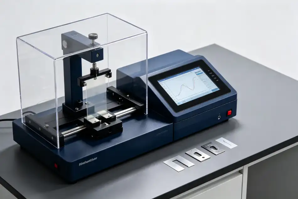
Four Tear Tests That Should Not Be Confused
| Method family | Loading principle | Typical material | Why it is different |
|---|---|---|---|
| ASTM D1922 / ISO 6383-2 | Pendulum propagation of a pre-cut tear | Plastic film and applicable sheeting | This is the Elmendorf film method covered by this guide. |
| ASTM D1004 | Low-speed tensile loading of a shaped specimen | Plastic film and sheeting | Different specimen, apparatus, speed and tear behavior; ASTM says the data may supplement D1922, not replace it. |
| ISO 6383-1 | Trouser-shaped specimen pulled in tension | Plastic film and sheeting | Part 1 is a trouser-tear method; Part 2 is Elmendorf. |
| Textile Elmendorf methods | Pendulum propagation using textile-specific specimens and rules | Woven and applicable textile fabrics | A similar machine name does not make the plastic and textile procedures interchangeable. |
DERUI's textile Elmendorf tearing tester should remain positioned around verified textile methods and textile specimen preparation. Plastic-film searches should route to the film-capable product configuration and this D1922/ISO guide.
Specimen Geometry, Cutting and the Initial Slit
ASTM D1922 cites a rectangular specimen and a specimen with a constant-radius testing length; the constant-radius form is the preferred or referee specimen. The selected cutter must create the complete geometry repeatably. A separate slit knife alone is not enough if the outer specimen dimensions and tear path vary from sample to sample.
The verified DERUI configuration includes an ASTM D1922 rectangular cutter, ASTM D1922 constant-radius cutter, ISO 6383-2 cutter, MD/TD sampling tool and dimensioned template drawings. Keep each tool identified by method and inspect cutting edges regularly. Dull blades can stretch, notch or roughen the film before testing.
Use a sharp, verified cutter on a suitable backing. Reject visibly stretched or damaged edges.
The verified device specification lists a 20 ± 0.5 mm initial cut. Confirm it against the selected standard and cutter before release.
Do not combine rectangular and constant-radius results in one historical dataset without an approved correlation.
Condition and handle the specimens according to the governing document and material specification. The equipment's permitted room environment—20 ± 10°C and relative humidity below 85%—is an installation limit, not a replacement for the standard specimen-conditioning requirement.
Machine Direction, Transverse Direction and Tear Direction
Extrusion, stretching and downstream converting can orient polymer chains and create pronounced anisotropy. The same roll may therefore produce very different tear resistance depending on specimen direction. ASTM notes that orientation, extensibility and oblique tearing can make some films much less reproducible than others.
Mark the machine direction (MD) on the parent roll before cutting. Prepare the two specimen sets separately and define direction according to the selected standard—usually by the direction in which the tear propagates, not merely the long edge of the coupon. This prevents an easy but serious reporting error: swapping the direction of specimen cutting with the direction of tear propagation.
Do not average MD and TD into one “film tear strength” unless the customer specification explicitly requires that calculation. Separate direction results are usually more useful for material selection and process troubleshooting.
Selecting a Valid Pendulum Range and Using Multiple Plies
The verified instrument uses a single pendulum and provides a stated measuring range of 10–16,000 mN with 0.1 mN minimum graduation. A wide displayed range does not mean every specimen will automatically produce a valid result. The tear must consume enough pendulum energy to be measured reliably without exceeding the instrument's verified operating range.
If one ply produces a result too close to the lower usable limit, multiple plies may be tested when the governing method permits it. The verified clamps can hold very thin, smooth film, their clamping force is adjustable, and the system supports multiple film plies. All layers must be aligned consistently, remain individually free to tear as required and be reported with the number of plies and the calculation used.
| Observed result | Likely risk | Corrective action |
|---|---|---|
| Near the lower verified limit | Resolution and friction effects become more influential | Use an authorized multiple-ply approach or a more suitable verified range. |
| Near or beyond the upper limit | Incomplete tear or over-range result | Use a higher-capacity verified configuration; do not extrapolate. |
| Layers stick together | The stack may not behave as independent plies | Review specimen preparation and method suitability before reporting a per-ply value. |
| Wide scatter within one direction | Orientation variation, thickness variation, slip or oblique tearing | Inspect each tear path and separate material variability from apparatus problems. |
Use the valid-result limits and multiple-ply calculation from the current authorized standard rather than inventing a universal percentage of full scale.
A Defensible Laboratory Workflow
- Confirm the governing method. Record ASTM D1922-23, ISO 6383-2:1983 or the exact customer material specification and authorized deviations.
- Identify the film. Record resin/structure, production lot, thickness, roll location, surface treatment, lamination and any aging or conditioning.
- Mark MD and TD. Do this on the parent film before cutting small specimens that no longer reveal web direction.
- Select and inspect the cutter. Use the correct rectangular, constant-radius or ISO tool. Check blade condition and verify critical dimensions at the required interval.
- Select the test range or ply count. Use preliminary specimens where permitted, then document the single-pendulum range and number of plies.
- Verify zero and apparatus condition. Inspect pendulum release, bearing freedom, clamps, spacing, cutter and calibration/verification status.
- Clamp without wrinkles or slip. Align the slit and free tear path consistently. Adjust clamp pressure only through the approved setup.
- Release and inspect every tear. Record the result, complete/incomplete tear, path deviation, slip and any abnormal specimen behavior.
- Calculate and report by direction. Include individual values, summary statistics, thickness, geometry, ply count, units and invalid-result handling.
When a Result Is Invalid—or Technically Misleading
Highly oriented film may leave the intended path. Apply the selected method's validity provisions; do not silently accept or delete it.
A smooth film moving in the clamp changes the effective tear geometry. Review clamp faces and pressure before repeating.
The pendulum may lack usable capacity or the material may be unsuitable for the chosen configuration. Do not extrapolate the display.
ASTM states that tearing force is not directly linear with thickness. Compare like thicknesses and report thickness.
Energy used to deform the specimen can make results variable or misleading. Demonstrate acceptable reproducibility for the material.
Do not call a textile, trouser-tear or tensile result “ASTM D1922” merely because the instrument measures tearing.
ASTM warns that reproducibility can vary greatly for highly extensible or highly oriented films. Specification acceptance should use D1922 only after the material has demonstrated acceptable reproducibility under the selected procedure.
Elmendorf Film Tear Tester Selection Checklist
The verified DERUI film configuration uses one pendulum, adjustable clamps capable of holding very thin smooth films, multiple-ply testing and dedicated ASTM/ISO cutting tools. The following table separates confirmed specifications from the additional documentation a buyer should request.
| Item | Verified configuration | Purchase/acceptance check |
|---|---|---|
| Measurement | 10–16,000 mN; 0.1 mN minimum graduation | Request calibration/verification coverage and usable limits across the stated range. |
| Indication performance | Indication error ±1%; indication variability ≤1% | Confirm test conditions, traceability and current certificate. |
| Pendulum geometry | Tear arm 104 ± 1 mm; initial angle 27.5 ± 0.5° | Verify against the ordered standard configuration. |
| Clamps | Spacing 2.8 ± 0.3 mm; adjustable force; suitable for thin smooth film | Run the customer's thinnest and most slippery film before final acceptance. |
| Initial cut | 20 ± 0.5 mm | Check blade condition and dimension with the selected method/cutter. |
| Specimen tools | D1922 rectangular and constant-radius cutters; ISO 6383-2 cutter; MD/TD tool; dimensioned drawings | List every tool in the quotation and acceptance checklist. |
| Interface/output | 7-inch touchscreen and integrated modular thermal printer | Confirm units, statistics, MD/TD fields, ply calculation and digital export. |
| Installation | 410 × 320 × 600 mm; 220 V, 50 Hz | Confirm local voltage/frequency and a stable, level bench. |
| Environment | Room temperature 20 ± 10°C; RH <85% | Treat this as equipment operating environment, not specimen conditioning. |
Review the film-capable tear strength test machine for the verified pendulum configuration. When browsing the broader tear and textile test equipment range, select by material, standard and specimen geometry rather than by the generic word “tear.”
For a technical review, provide the standard and edition, film structure, nominal thickness, MD/TD, expected tear range, whether multiple plies are permitted, specimen geometry and required report units. DERUI can then confirm the cutter set, clamping setup, usable measurement range and data configuration.
Frequently Asked Questions
Are ASTM D1922 and ISO 6383-2 equivalent?
ASTM D1922-23 states that it is equivalent to ISO 6383-2. Use the exact method and edition named by the customer and follow its specimen, validity and reporting requirements.
What does the Elmendorf test measure?
It measures the average force required to propagate an already initiated tear through plastic film or applicable non-rigid sheeting under pendulum conditions.
Is Elmendorf tear the same as ASTM D1004?
No. ASTM D1004 uses a shaped specimen in a tensile-testing machine at low crosshead speed. D1922 uses a pre-cut specimen and a pendulum. Results are not interchangeable.
Why must MD and TD be tested separately?
Film processing creates molecular orientation, so tear propagation can differ sharply by direction. Keep MD and TD specimens, results and statistics separate.
Can several film layers be tested together?
Yes, when the selected method permits it and one ply is below the usable range. Record the number of plies, align them consistently and apply the authorized calculation.
What causes an oblique tear?
Film orientation, extensibility, thickness variation, cutting defects or misalignment can make the tear leave its intended path. Apply the method's validity rule and document the path.
What information is needed to select a tester?
Provide the method, film type and thickness, MD/TD, expected force, specimen geometry, ply count and required units/statistics. A maximum force alone is not enough.
ASTM D1922-23 ·
ISO 6383-2:1983
This guide explains method selection and equipment considerations; it does not reproduce the copyrighted procedures. Use the current authorized standard, customer specification and laboratory scope for the actual test.