

Small Tensile Tester Selection: Low-Force Measurement, Grips and Travel
Date: October 21, 2026 Categories: Buying Guides Views: 5474
Small Force Needs More Than a Small Frame
When a specimen breaks at a low force, the largest capacity on the brochure is only one part of equipment selection. The useful questions are whether force can be measured in the required interval, whether gripping changes the specimen response and whether the test can reach its endpoint.
This guide concentrates on low-force work. For the broader choice of single-column, dual-column or larger equipment, use the existing benchtop tensile tester selection guide.
Write Down the Forces That Matter
State minimum, routine and expected maximum results. Include any preload and the smallest change that affects the decision. Give the supplier those values in explicit force units.
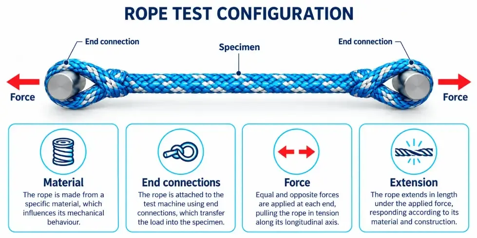
A capacity labelled “5 kg” in equipment literature needs clarification as a force rating. If it means 5 kgf, the standard conversion gives approximately 49.0 N. This is a unit illustration, not a claim that any particular machine has a verified interval down to a chosen lower endpoint.
Do not select from a blanket percentage rule. Ask for calibration or verification performance covering the interval you need. A larger cell may survive a higher load but still fail to answer the low-force measurement question.
Keep Resolution Separate from Accuracy
Resolution describes an increment or representation. Accuracy and uncertainty describe different aspects of how a measurement relates to a reference. A fine displayed number is not proof that every digit represents a reliable material difference.
Ask which error basis is used: percentage of reading, percentage of full scale, an absolute term or a combination. Also ask where that statement applies. Avoid rewriting these definitions into one interchangeable “high precision” claim.
The requirement is practical: can two low-force samples be compared with measurement performance suitable for the laboratory’s decision? The manufacturer’s verified interval and supporting records are more useful than a large resolution ratio by itself.
Fit the Load Train into the Available Space
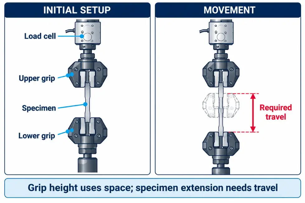
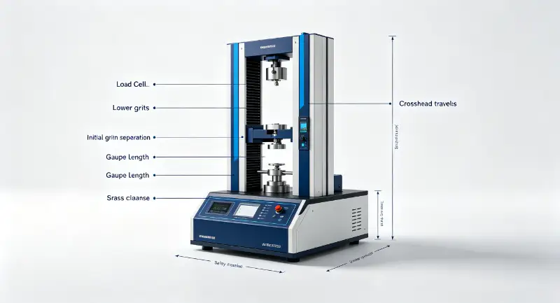
The installed load cell, adapters and both grips consume test space before the specimen is loaded. Initial grip separation must fit within the remaining space. Crosshead stroke describes available movement, not the initial space between contacts.
For a simple planning example, a 50 mm reference length with 200% extension corresponds to a 100 mm increase over that reference length. It does not establish total machine height or automatic suitability. Add the setup allowances relevant to the procedure and confirm the geometry with the actual grips.
Keep direct strain measurement separate where required. Crosshead movement can include grip motion, seating and system compliance.
Use Representative Specimens to Choose Grips
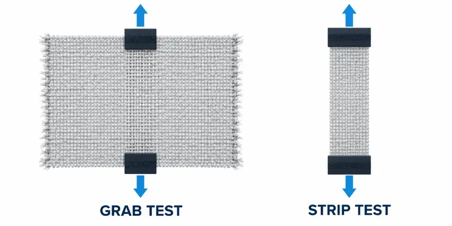
Grip mass, contact geometry and sample alignment can be consequential in low-force work. Thin films, fibres, delicate fabrics and small assemblies do not necessarily use the same contact arrangement.
Pull-out
Observe whether the specimen moves relative to its grip contact. A smooth curve does not by itself exclude slip.
Local damage
Inspect whether contact pressure or a jaw edge causes premature failure.
Geometry changes
For peel or component pulls, confirm the required direction and fixture movement rather than treating every test as straight tension.
Ask for a trial record that identifies the sample, settings and failure observations. A trial should test the intended configuration, not merely demonstrate that the frame can move.
Agree the Report and Acceptance Evidence
Specify force result definitions, movement or strain results, units and the raw data or export you require. Material stress additionally needs valid specimen dimensions; modulus is not automatically meaningful from a generic force–movement record.
List the selected sensor, fixtures, travel limits and verification evidence in the acceptance scope. Include practical overload handling and the operator’s setup process. Routine zeroing should not be represented as a full calibration.
This creates a clearer comparison between suppliers: the same specimen, force interval, measurement definition and deliverables rather than capacity labels alone.
Match the Product to the Scope
Review the DR-L201-1 small tensile testing machine when its nominal low-force configuration fits the project. For dedicated fabric or peel work, compare the material-specific arrangement instead of assuming a generic frame includes every accessory.
An initial enquiry can be short: sample photograph, intended result and approximate force if known. A drawing or an existing report helps resolve the remaining questions.
Send a Low-Force Test Requirement
Describe the specimen and decision you need to make. Ask for the verified measurement interval, grips, usable space and reporting scope together.