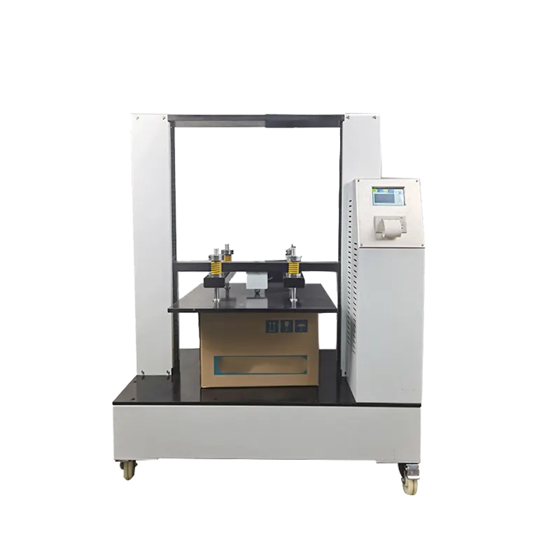
STEP 01
Define the Test Object
Identify an empty box, completed filled package, container component or unit load. Record construction, closure, contents, internal supports, dimensions, weight and loading orientation.
Material testing equipment configured for your test method and specimen.
Packaging Compression Test Equipment
Evaluate the compressive resistance and stacking performance of corrugated cartons, completed transport packages and other containers under controlled platen loading. Choose a system from the package footprint, height, expected force, required test procedure and results—not from maximum capacity alone.
01 · DEFINE THE PACKAGE
Specify whether you are testing an empty corrugated box, a filled transport package or another container. Provide its dimensions, construction, closure, contents and the required procedure.
02 · SIZE THE SYSTEM
Match the expected working and failure loads to a usable measurement range. Confirm platen footprint, clear opening, package height and required compression travel before selecting a frame.
03 · DEFINE THE OUTPUT
Identify whether you need peak force, deformation, load hold, loading rate, elapsed time or pass/fail results. The procedure determines the required controls, sensors and report fields.
Verified DERUI configuration range
Current DR-B211 configurations include 10, 20 and 50 kN maximum-force options, test spaces up to 1300 × 1500 × 1500 mm, 0.1–200 mm/min lift speed and load precision within ±0.5%. Final suitability must be reviewed against the package, selected method, force range and verification requirements.
For an accurate recommendation, send the package details first.
Include package dimensions and weight, empty or filled condition, expected compression load, required test method, result fields, test frequency and available electrical supply.
Explore box and packaging compression testers for corrugated cartons, completed transport packages and other packaging compression applications. Compare available systems by force range, platen dimensions, clear test height, compression travel, control functions and reporting requirements. Additional tester configurations and application-specific systems will be added to this section. Open each product page to review its specifications and confirm suitability for your package, test method and required results.
A capacity value does not define the complete test system. Confirm how force is applied, measured, controlled and reported for the package and procedure.
Confirm that the load cell and verified working range cover both the expected peak load and the lowest force that must be reported.
Check package width, depth and height together with required compression travel, platen clearance and loading access.
Define test speed, preload, maximum force, deformation limit, hold time and pass/fail logic required by the selected procedure.
Review overload protection, travel limits, emergency stop, guarding needs, displayed results and exportable report fields before ordering.
Selection and Method Planning
Start with the package and required procedure—not with the machine capacity. The test object, loading orientation, expected force, package envelope, control mode and report requirements determine the appropriate configuration.
STEP 01
Identify an empty box, completed filled package, container component or unit load. Record construction, closure, contents, internal supports, dimensions, weight and loading orientation.
STEP 02
Specify the current standard edition or internal method, specimen preparation, conditioning, platen type, speed or loading control, termination point and required result calculations.
STEP 03
Match the expected working and failure loads to the usable force range. Confirm platen footprint, clear height, compression travel, speed range and electrical requirements.
STEP 04
List peak force, deformation, hold load and time, pass/fail rules, curves, report fields and data export. Confirm force verification, installation, training and acceptance requirements.
These references cover different scopes. Confirm the complete procedure before claiming method compatibility.
| Reference | Primary scope | Configuration points to confirm |
|---|---|---|
| ASTM D642 | Compression resistance of shipping containers, components and unit loads; containers may be tested with or without contents. | Loading orientation, fixed or swiveled platen, force range, loading procedure and termination criteria. |
| ISO 12048 | Compression and stacking tests for complete, filled transport packages using a compression tester. | Complete filled specimen, load application, stacking condition, deformation or failure criteria and reporting. |
| TAPPI T 804 | Compression resistance of corrugated or solid fiberboard shipping containers, empty or with packing and contents as required. | Container condition, test direction, platen arrangement, force and deformation measurement. |
| ISTA 3A | General simulation procedure for individual packaged products shipped through parcel delivery systems at 70 kg (150 lb) or less. | Compression is only part of a broader sequence that can include conditioning, vibration, drop and impact. Additional equipment is required for the complete procedure. |
Package drawing or dimensions; empty or filled condition; contents and internal supports; expected load; selected method and edition; largest deformation; required results; tests per day; report format; electrical supply and installation space.
Send the procedure and package details for a force-range, test-space, control and reporting review.
A box compression tester applies a controlled compressive load to a corrugated box, completed transport package or other suitable container between two platens. It measures force and displacement as the specimen deforms, reaches a specified limit or fails.
The result describes the specimen under the selected preparation, orientation, environment and procedure. It does not reproduce every vibration, impact, handling or climatic condition encountered during distribution.
Evaluates a finished box or package as a structure. Geometry, board construction, joints, closures, contents, internal supports, orientation and conditioning can influence the result.
Evaluates the edgewise compression resistance of a corrugated board specimen. ECT is a material or board-level result and does not replace testing the completed box.
Compare available force capacities, test spaces, compression travel, control functions, safety protection and report options before selecting a configuration.
This example shows how a representative transport package was prepared, configured and evaluated on a DERUI box compression tester.
The settings and results apply only to the specimen and conditions documented below. Replace every placeholder with information from the same real test before publishing.
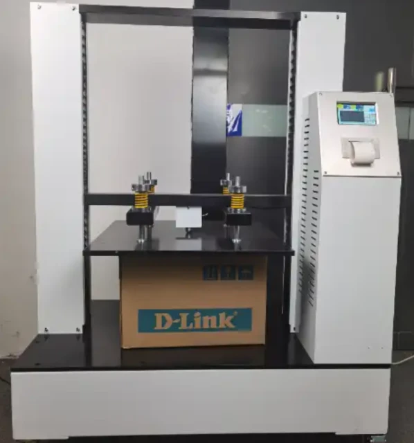
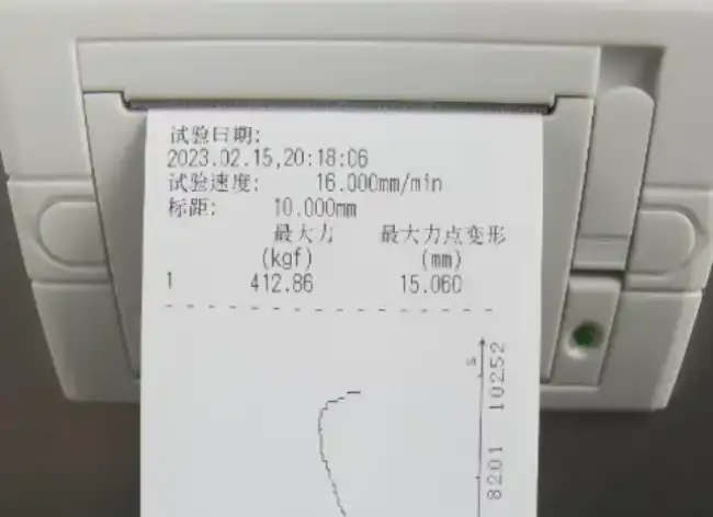
Equivalent to the printed result of 412.86 kgf, converted using 1 kgf = 9.80665 N.
Recorded deformation at the point of maximum force.
Crosshead or platen speed displayed on the supplied test result printout.
Send the package dimensions, weight, expected load, test method and required results for a technical review.
Applications and Decisions
Compression data is most useful when representative packages are tested under controlled, documented conditions.
Use the result together with package design, contents and the wider distribution test plan—not as a stand-alone guarantee of shipping performance.
INCOMING QUALITY
Compare: Representative boxes from suppliers, production lines or incoming lots against an approved specification or control sample.
Control: Board grade, dimensions, closure, orientation, conditioning, sample history and test settings.
DESIGN COMPARISON
Compare: Flute combinations, dimensions, joints, closures, partitions and other packaging constructions.
Supports: Selection of candidates for further package validation; it does not alone prove distribution performance.
LOAD REVIEW
Evaluate: Peak resistance, deformation at a selected load, or behavior during a specified hold load and duration.
Define: Target load, duration, deformation limit, orientation, acceptance criteria and environmental condition.
FAILURE ANALYSIS
Review: Failure location, panel buckling, joint or closure behavior, deformation pattern and force-deformation curve.
Supports: Root-cause investigation when combined with handling, vibration, drop, climate and supply-chain evidence.
A complete distribution evaluation may also require drop, vibration, impact, clamping or climatic conditioning according to the selected test plan.
Equipment Selection, Test Methods and Result Interpretation
Provide the maximum package length, width and height, its loading orientation and whether it will be tested empty, filled or as part of a unit load. Confirm that the platen footprint, clear height, loading access and compression travel accommodate the specimen throughout the test.
State the routine working load, expected peak or failure load and the lowest force that must be reported. The machine, force transducer and verified working range should cover the required measurements without relying only on the frame’s maximum rated capacity.
Specify the applicable ASTM, ISO, TAPPI or customer procedure, together with the loading orientation, test speed or control mode, hold time, stop condition and required report fields. These requirements determine whether a proposed configuration is suitable beyond its physical size and force rating.
Confirm the current ASTM, ISO, TAPPI, ISTA or customer procedure, the test objective and the package condition. Record whether the specimen is empty or filled, its loading orientation and any required conditioning before choosing machine settings.
Specify whether platen movement, force application or another method-defined variable controls the test. The programmed speed or loading rate should remain within the machine’s controllable range and be reported with the result so repeat tests can use the same conditions.
Define whether the test ends at peak-force loss, a maximum force, a deformation limit, a specified displacement or another acceptance criterion. For stacking or hold-load work, also specify the target load, hold duration and pass/fail rule before testing begins.
Check the largest package footprint and height against the usable compression space, platen dimensions, daylight and available travel. The package must be loaded safely and remain correctly positioned throughout the required deformation or hold period.
Confirm that the force transducer and verified working range cover the expected loads, and that the controller can apply the required speed, force, displacement, hold time and stop conditions. Platen alignment, frame stiffness and the selected fixed or swiveling arrangement must match the intended procedure.
A suitably configured UTM may be useful when a laboratory also performs tension, flexure or material-level compression tests. A dedicated box compression tester is usually easier to justify when large packages, frequent production checks, simplified loading and packaging-specific reports are the main priorities.
A preliminary design comparison, routine production check, supplier qualification, customer acceptance test and failure investigation do not require the same level of evidence. State the decision, acceptance criteria and consequences before choosing the sample count.
Corrugated board, converting, joints, closures, filling, orientation and conditioning can all change compression results. The sampling plan should represent the relevant production lots, suppliers, machines or designs instead of testing many specimens from only one convenient source.
Decide whether the report needs individual results, an average, variation, confidence limits, a comparison between designs or pass/fail against a specification. A qualified quality or statistics function should set the required sample size when formal confidence or acceptance decisions are required.
Confirm the retailer, sales channel, package type, product category, weight, dimensions, fragility and shipment method. These details determine which current procedure, test type, sample requirement and reporting path applies. Use the latest program documents because retailer and ISTA procedures can change.
Depending on the selected program, the packaged product may also require conditioning, drop or shock, vibration, clamp or handling tests and post-test product evaluation. Follow the prescribed sequence and acceptance criteria; a stand-alone BCT result does not demonstrate performance against hazards that were not tested.
Verify the required equipment characteristics, laboratory or personnel qualifications, specimen count, report template, photographs and submission process. The machine supplies test data for a defined step; the responsible program owner, retailer or qualified laboratory determines whether the complete evidence is acceptable.
Provide the program name and current procedure edition, package classification, product and packaged weight, dimensions, shipment method, required compression orientation, target load or calculation, test sequence, acceptance criteria, laboratory requirements and report template. Do not configure the machine from the retailer name alone.
The package should contact the platens in the orientation required by the procedure. Excessive tilt, damaged platen surfaces, debris or off-center placement can concentrate force on one wall, edge or corner and produce a failure that does not represent the intended loading condition.
Fixed and swiveling platens do not necessarily produce the same loading condition. Confirm the platen arrangement, contact faces and permitted package orientation from the selected ASTM, ISO, TAPPI or customer procedure before comparing results.
Keep platen surfaces clean and undamaged, check mounting and mechanical play, and verify the applicable geometry or alignment characteristics according to the machine instructions and laboratory quality plan. Investigate unusual contact patterns, asymmetric collapse or a sudden change in repeatability before accepting the data.
Decide whether the test supports comparison at a standard laboratory atmosphere, evaluates a specified storage condition or investigates a particular distribution risk. Use the conditioning atmosphere and duration required by the current test method, customer specification or approved test plan rather than applying one universal condition.
Keep package construction, contents, closure, orientation and exposure history consistent across the comparison. Record the conditioning set points, tolerances, duration, specimen arrangement and any evidence that the packages reached the required state before testing.
After conditioning, follow the method-defined transfer and testing window so specimens do not gain or lose significant moisture before loading. Record the environment during testing, actual transfer time and any deviations. Testing inside a controlled chamber requires a separately reviewed chamber, platen access, force range and control configuration.
Record the conditioning method and edition, chamber set points and observed conditions, exposure duration, package and contents, specimen orientation, time between conditioning and testing, test-room conditions and any deviation from the planned procedure. This information allows another laboratory or production team to understand why results from two test series may differ.
Include peak force, deformation at peak and any force or deformation measured at a specified point. Where required, report the force–deformation curve, hold load and duration, pass/fail result, test endpoint and reason for stopping. Use only result fields supported by the configured measurement and software system.
Identify the package construction and contents, specimen ID and production lot, loading orientation, conditioning, test method and edition, platen arrangement, speed or control mode, force range and any deviation. Without this context, two similar peak-force values may represent different tests.
Compression results can support package comparison, quality limits and engineering estimates for stacking. Final limits should also consider duration under load, humidity, contents, pallet pattern, load sharing, handling, safety factors and the applicable warehouse or distribution requirements. A calculated value should therefore state its assumptions and not be presented as a universal safe stacking height.
Use the same package orientation, conditioning, contents, test method, machine settings and result definitions. Compare individual results and variation—not only the averages—and document visible failure locations so the force data can be connected to the package structure.
Keep platen surfaces clean and free from debris. Check guards, emergency stop, travel limits, cables, fixtures and visible fasteners, and look for damage, abnormal movement, unusual noise or changing contact patterns. Do not continue testing when a condition could affect safety or the load path.
Follow the model-specific schedule for lubrication, drive components, bearings or guides, platen mounting, electrical connections and safety devices. Service frequency should reflect operating hours, package debris, load severity, environment and previous inspection findings rather than an invented universal interval.
Define the required force range, directions, verification points, displacement or speed checks and acceptance criteria. Review measurement performance after relocation, overload, relevant repair, force-transducer replacement, impact or unexplained result shift, even when the routine verification due date has not arrived.
Keep equipment identification, inspection and maintenance logs, repair history, verification certificates and results, as-found and as-left conditions, applicable force ranges, environmental conditions, reference-equipment traceability and the person or provider completing the work. Link each test report to the equipment status valid on the test date.

Derui Test Equipment
We are a dedicated manufacturer of precision material testing equipment, committed to supporting global industries with reliable testing solutions.
Our Core Product Lines:
Universal Testing Machines (Tensile/Bend/Compression)
Environmental Simulation Chambers (Climatic, Thermal Shock)
Specialized Testing Equipment for Packaging, Furniture & Materials