Six Configuration Decisions Before Quotation
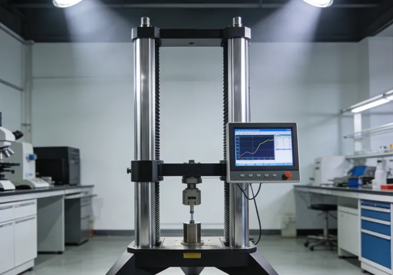
Choose a Floor-Standing UTM from the Test Requirements
A model number or maximum-force rating is not enough. Define the complete test and measurement chain so the quotation covers the specimen, required results, fixtures, sensors, controls and installation conditions.
01 · DEFINE THE TEST
Start with the Governing Method and Specimen
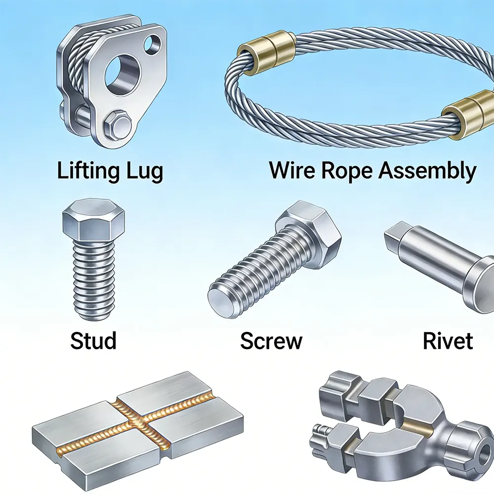
Provide the current test procedure or customer specification, material or component, specimen drawing, dimensions, loading direction, test mode and required result. A standard number alone may not identify the applicable section, specimen geometry or reporting requirement.
Send before quotation: method edition and section, specimen drawing, material condition, expected failure mode, required calculations and acceptance criteria.
02 · SIZE THE LOAD RANGE
Define the Expected Working and Peak Loads
Estimate the force from representative data, specimen section and expected strength, then distinguish routine working loads from the highest anticipated event. Capacity must cover the test, while the selected load cell and verified range must also resolve the lowest measurements that matter.
Confirm: minimum useful force, normal working force, expected peak or break force, preload, hold requirements and overload risk.
03 · FIT THE COMPLETE SETUP
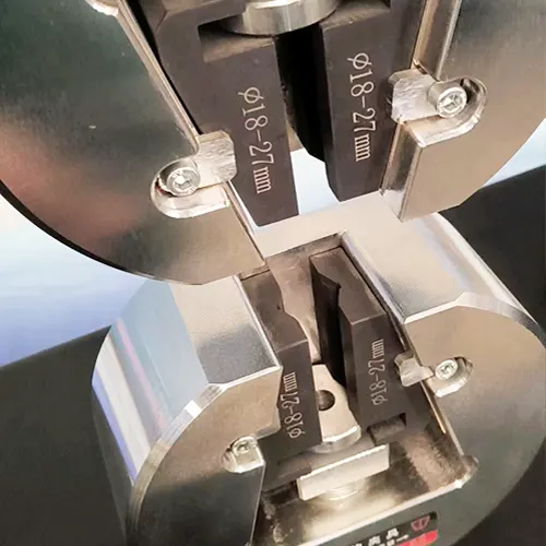
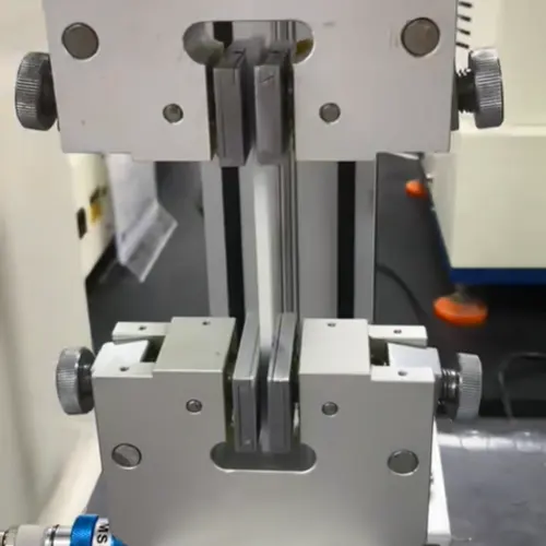
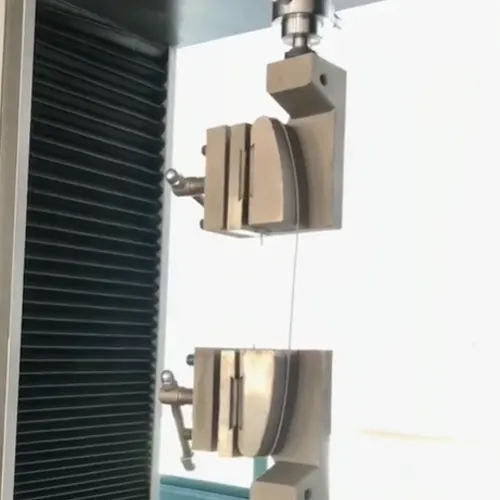
Check Usable Test Space and Tooling
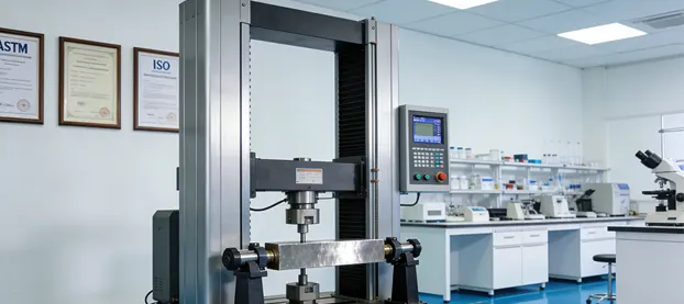
Compare grip separation, crosshead travel, column clearance and daylight after accounting for grips, adapters, fixtures, specimen length, extensometers and any environmental accessory. Nominal frame height is not the same as usable test space.
Confirm: specimen dimensions, required travel, grip and fixture envelope, support span, loading access, changeover method and accessory clearances.
04 · DEFINE THE MOTION
Match Speed and Control to the Procedure
List the required speed or loading rate, ramps, holds, stage changes, stop conditions and any load-, displacement- or strain-control requirement. Do not assume that every controller or software package supports every control transition or calculation.
Confirm: speed range at load, control mode, rate tolerance, dwell time, sampling need, break detection, return sequence and software method.
05 · DEFINE THE MEASUREMENT
Specify Force and Strain Measurement
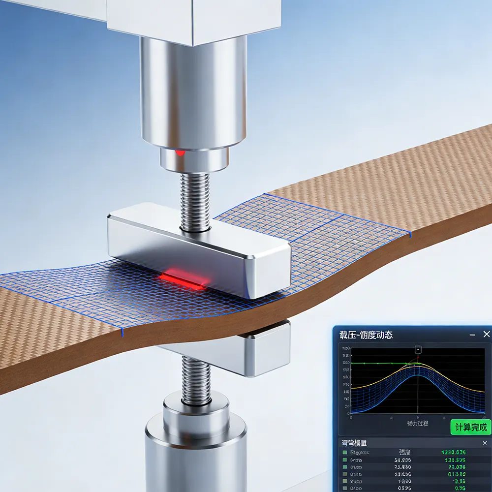
Select force measurement from the required working range and verification class—not only the frame capacity. When the result depends on specimen strain, define the extensometer type, gauge length, travel, strain range, attachment restrictions and verification requirement.
Confirm: force range and class, extensometer or auxiliary sensors, channels, sampling, calibration or verification scope, calculations and exported data.
06 · PLAN THE INSTALLATION
Review Site, Safety and Lifecycle Requirements
Check the machine footprint, mass, access route, floor condition, power and any air, cooling or hydraulic services. Include guarding, fixture handling, installation, training, verification, maintenance, spare parts and software support in the procurement scope.
Confirm: destination and power, door and lifting access, floor space, specimen hazards, guarding, commissioning, training, service responsibility and required documentation.