
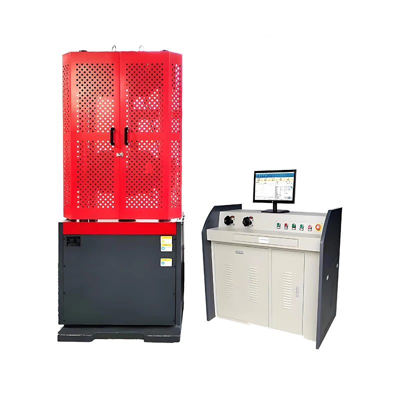
Select a hydraulic universal testing machine based on your material, specimen dimensions, test method and maximum required force—not on load capacity alone. DERUI hydraulic UTMs can be configured for high-force static tensile, compression, bend and proof-load testing of metals, steel rebar, fasteners and structural specimens.
These systems are intended for laboratories and production quality-control teams that need more loading capacity, working space or fixture flexibility than a standard low-force universal testing machine can provide. The correct configuration must accommodate both the expected breaking load and the specimen itself, including its diameter or thickness, gripping length, required clearance, expected extension and loading direction.
A complete hydraulic testing system may include the load frame, hydraulic power unit, force measurement system, digital controller, tensile grips, compression platens, bend fixtures, extensometer and test software. Each component affects the usable test range and the results that can be reported. For example, measuring yield strength or proof stress normally requires suitable strain measurement, while testing rebar, flat metal coupons or finished components may require different jaws or purpose-built fixtures.
Depending on the selected machine, grips, extensometer, control functions and verification requirements, a system can be configured for specified methods such as ASTM E8/E8M, ASTM E9, ASTM E290, ISO 6892-1 and ISO 7438. Final compatibility must be checked against the current method edition, specimen geometry, loading procedure, measurement range and reporting requirements before ordering.
Send DERUI your material, test method, expected maximum load and specimen drawing. The engineering review will identify the required frame capacity, usable force range, tensile and compression space, piston stroke, grips, extensometer, controller and installation conditions before a model is recommended.
Maximum force is only the first selection point. Compare the usable force range, tensile and compression space, piston stroke, grip capacity, extensometer compatibility, control mode, and required test results before choosing a model.
Static Hydraulic UTM or Dynamic Servo-Hydraulic System?
“Hydraulic” does not automatically mean that a machine is fatigue-rated. Define the required test type before selecting the actuator, controller, sensors, grips and fixtures.
Static Hydraulic UTM
• Monotonic tensile testing
• Compression and proof-load testing
• Bend testing with the required fixture
• Load-hold or controlled loading when supported
Use this route for routine high-force quality control and static material characterization.
Dynamic Servo-Hydraulic System
• Requires a fatigue-rated actuator and load train
• Requires confirmed frequency, waveform and amplitude
• Requires a suitable servo valve, controller and data acquisition system
• Requires fatigue-rated grips, sensors and safety provisions
A dynamic system should be presented only after its dynamic force, frequency, waveform and amplitude ratings are confirmed.
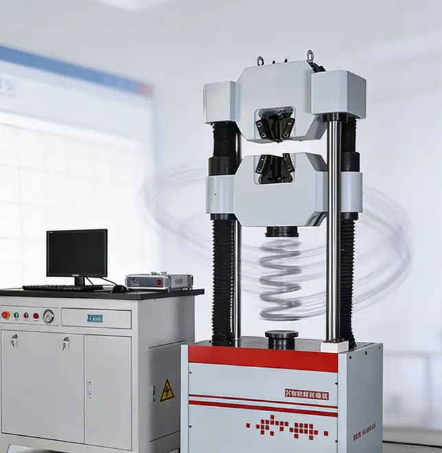
A hydraulic universal testing machine uses a hydraulically powered loading system to apply controlled high-force tension, compression or bending loads. A complete system combines the load frame, hydraulic power unit, force measurement, displacement measurement, controller, grips or fixtures and test software.
The machine name alone does not establish compliance with a test method. Compatibility depends on capacity, usable force range, test space, control capability, grips, extensometer, software procedure and verification status.
| Reference | Purpose | Configuration to confirm |
|---|---|---|
| ASTM E8/E8M / ISO 6892-1 | Metallic materials tensile testing | Grips, test-rate control, extensometer and calculations |
| ASTM E9 | Compression testing of metallic materials | Compression fixtures, alignment and deformation measurement |
| ASTM E290 / ISO 7438 | Bend testing of metallic materials | Supports, loading nose, span and fixture capacity |
| ASTM E4 / ISO 7500-1 | Force verification of testing machines | Force range, class, verification points and documentation |
| ASTM E83 / ISO 9513 | Extensometer verification | Type, gauge length, range and required class |
Confirm the current standard edition, specimen, procedure and reporting requirements before ordering.
Planning force verification for your testing machine?
Review ASTM E4 and ISO 7500-1 accuracy classes, force ranges
and verification documentation.
The system converts hydraulic pressure into controlled specimen loading while force, displacement and—when required—strain are measured through separate feedback channels.
Install and align the specimen
The operator selects rated grips or fixtures, establishes the required test space and aligns the specimen with the loading axis.
Configure the test procedure
The method defines control mode, loading rate, limits, data channels, calculations and stop conditions.
Apply controlled hydraulic load
The hydraulic power and control system moves the actuator while the controller regulates the ordered force or displacement profile.
Measure force, displacement and strain
The force transducer and displacement channel record machine response; an extensometer is used when direct specimen strain is required.
Calculate and review results
Software displays curves and calculates only the properties supported by the configured method and measurement channels.
Match the specimen, loading direction, grips, fixtures and strain-measurement system to the required test method.
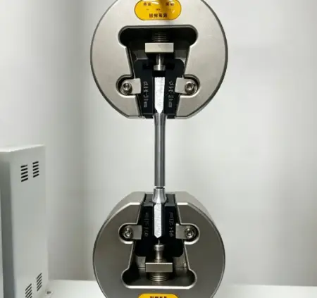
Configure the hydraulic universal testing machine for static tensile testing of steel rebar, round metal bars and flat metallic specimens.
Typical specimens: Reinforcing bar, round bar, flat metal coupons and machined tensile specimens.
Required configuration: Select round-specimen or flat-specimen jaws according to the diameter, thickness, width, surface condition and expected maximum load. Confirm that the tensile space accommodates the gripping length and expected extension.
Strain measurement: A suitable extensometer is normally required when yield strength, proof stress, modulus or elongation must be measured directly from the specimen.
Method planning: Configurations may be reviewed for specified methods such as ASTM E8/E8M or ISO 6892-1 after the specimen, test rate, grips, extensometer and reporting requirements are confirmed.
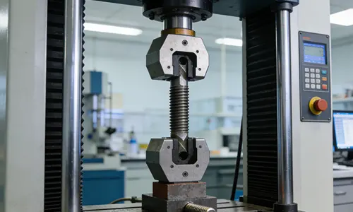
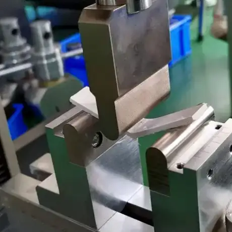
Choose the system from the specimen, test method, working load range, test space, grips, measurement requirements and site conditions—not from capacity alone. Use the seven checks below to prepare an accurate configuration request.
Define the Specimen
Provide the material, dimensions or drawing, gripping section, expected failure mode and loading direction.
Define the Test Type
Specify monotonic tension, static compression, bend testing, proof loading or another required procedure. A static hydraulic UTM should not be assumed to support fatigue testing.
Define the Required Results
List the required force, strength, yield, proof stress, elongation, modulus, displacement or pass/fail results. These outputs determine the required sensors and software.
How should I select the force capacity of a hydraulic universal testing machine?
Define the Test Loads
Provide the routine working load, estimated maximum load and expected breaking load for each specimen and procedure.
Check the Usable Measurement Range
Confirm which force-transducer and verified range cover both the highest and lowest forces that must be reported.
Review the Complete Load Path
The frame, force transducer, grips, fixtures, adapters and fasteners must all suit the intended load and loading direction.
What maintenance should be planned for a hydraulic universal testing machine?
Inspect Before and During Use
Check for hydraulic leaks, damaged hoses, unusual noise, loose guards, contaminated grips, worn jaw faces and abnormal force or displacement readings. Stop and investigate unsafe conditions.
Maintain Oil, Filters and Seals
Monitor hydraulic-fluid condition and level, filter indicators, reservoir cleanliness, seals and cooling or ventilation. Replace oil and filters only using the specified grade, procedure and interval.
Plan Verification and Service Records
Maintain records of inspections, repairs, oil and filter changes, force verification and extensometer verification. Recheck measurement performance after relevant repairs, relocation or overload events.
Can a static hydraulic universal testing machine perform fatigue tests?
Define Static or Cyclic Loading
Specify whether the requirement is monotonic tension, compression, bending or proof loading, or a repeated cyclic test with defined waveform, frequency, amplitude and number of cycles.
Confirm Every Fatigue-Rated Component
Fatigue testing requires a compatible actuator, servo valve, controller, force measurement, grips, fixtures, load train and safety system rated for the intended cyclic loading.
Review the Exact Dynamic Configuration
Static force verification does not establish dynamic-force accuracy. The machine, specimen, waveform, frequency and configuration must be reviewed against the applicable fatigue method and verification requirements.
When does a hydraulic universal testing machine need an extensometer?
Define the Required Results
An extensometer is normally required when the report must include modulus, yield or proof strength, accurate strain, or elongation measured over a defined gauge length.
Separate Specimen Strain from Machine Movement
Actuator or crosshead displacement also includes grip seating, frame compliance and load-train deformation. It can therefore overstate the strain occurring in the specimen.
Match the Extensometer to the Test
Confirm the governing method, gauge length, strain range, expected elongation, specimen geometry, attachment method and required verification class before selecting the device.
What do ASTM E4 and ISO 7500-1 verify on a hydraulic UTM?
Identify the Force System
Define whether tension, compression or both must be verified and identify the force indicator, transducer and measurement ranges that will be used.
Specify the Required Range and Class
The requested force range, verification points, direction and accuracy or class must cover the loads that will actually be reported—not only the machine’s maximum capacity.
Separate Force Verification from Method Compliance
Force verification alone does not confirm grips, alignment, extensometer performance, test speed, software calculations or compliance with a material test method. These items require separate review.
What site, foundation and utility information is needed before installation?
Check Delivery and Lifting Access
Provide door widths, corridor and turning limits, ceiling height, floor level, unloading method and available crane, hoist or forklift capacity. Include the proposed equipment position.
Confirm Floor, Space and Utilities
Review the model-specific mass, footprint, floor or foundation instructions, anchoring, power supply, ventilation or cooling needs and clearance for operation and maintenance.
Plan the Complete System Layout
Allow for the frame, hydraulic power unit, controller, computer, guards and accessory handling. Hose and cable lengths, operator access and service clearance must be confirmed before shipment.
What information should I send for a hydraulic UTM quotation?
Define the Test and Results
Send the material, governing ASTM, ISO or customer method, loading type and required results such as strength, yield, proof stress, elongation, displacement or pass/fail.
Provide Geometry and Expected Loads
Attach a specimen drawing or dimensions, gripping section, routine load, estimated maximum or breaking load, required test space and expected extension or travel.
Confirm Accessories and Destination
State the required grips, fixtures, extensometer, guards, software or report needs, destination country, available power, installation conditions and requested documentation.
How do I choose grips for rebar, round bars and flat metal specimens?
Define the Specimen
Provide whether the specimen is rebar, a smooth round bar, a threaded component or a flat coupon, together with its diameter, thickness, width and gripping length.
Match the Jaw Geometry
Vee-profile jaws are commonly used for round specimens and rebar; flat jaws are used for rectangular or flat specimens. Jaw range and face profile must match the actual specimen.
Check Load, Surface and Alignment
Confirm the grip and jaw ratings, tooth or surface style, insertion depth and alignment. The setup should prevent slippage, jaw breaks and off-axis loading without damaging the required gauge section.

Derui Test Equipment
We are a dedicated manufacturer of precision material testing equipment, committed to supporting global industries with reliable testing solutions.
Our Core Product Lines:
-
Universal Testing Machines (Tensile/Bend/Compression)
-
Environmental Simulation Chambers (Climatic, Thermal Shock)
-
Specialized Testing Equipment for Packaging, Furniture & Materials
-

- Scan to chat on WhatsApp


