Compact Electromechanical Universal Testing Systems
Benchtop Tensile Testing Machines
Configure a compact universal testing machine for tensile, compression, bend, peel and component tests. Start with the specimen, test method, expected force range, required test space, grips and strain measurement—not with maximum frame capacity alone.
Define the test before selecting the frame
Provide material, dimensions, gripping section, procedure and results to be reported.
Confirm expected working and break loads, grip separation, travel and specimen extension.
Match grips, fixtures, load cell and extensometer to the specimen and required calculations.
Product Range
Choose a Benchtop UTM by Specimen, Force and Test Space
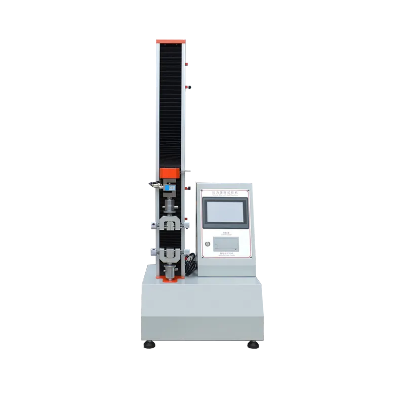
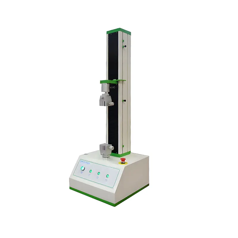
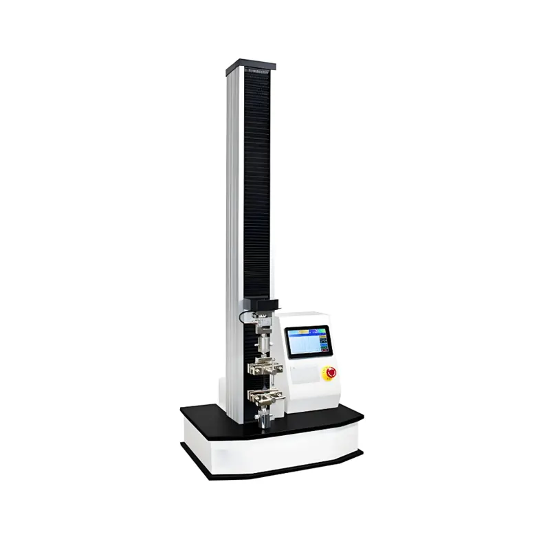
Compare the available single-column and dual-column systems by usable force range, vertical test space, crosshead travel, speed range and compatible grips. Open each product page for its current specifications, then send the specimen and method details for final configuration review.
CONFIGURATION AUDIT
Capabilities to Confirm Before Selecting a Benchtop UTM
A compact footprint does not define a complete test system. Confirm how the specimen will be loaded, measured and reported before selecting the frame.
Expected working and break loads
Match the load cell and verified working range to both the highest and lowest forces that must be reported.
Grip separation and travel
Check specimen length, grip body height, initial separation, expected extension and required crosshead travel.
Grips, fixtures and alignment
Select gripping faces and rated fixtures for the material, geometry, surface and loading direction.
Force, displacement and strain
Define required calculations, extensometry, data rate, control mode, stop conditions and report fields.
APPLICATION PLANNING
Match the Specimen to the Grip and Measurement Method
The frame is only one part of the system. Suitability depends on specimen geometry, surface, expected force, deformation behavior and the results required by the procedure.
Tensile, peel and puncture-related fixtures
Confirm jaw face, grip pressure, specimen width, gauge length, low-force measurement and whether direct strain measurement is required.
High extension and slip control
Review grip separation, expected elongation, jaw type, break detection and extensometer travel or non-contact measurement needs.
Peel, pull-off and assembly fixtures
Provide loading direction, bonded area, component drawing, adapter interface and acceptance criteria.
Platens, supports and loading noses
Confirm specimen envelope, span, radii, alignment, deflection measurement and fixture load rating.
EQUIPMENT DEFINITION
What Is a Benchtop Tensile Testing Machine?
A benchtop tensile testing machine is a compact electromechanical universal testing system that applies controlled load or displacement to a specimen through interchangeable grips or fixtures. A configured system combines the load frame, drive, force transducer, controller, test software and the accessories required by the procedure.
The machine name alone does not establish method compliance. The specimen, force range, test space, speed, grip design, strain measurement, calculations and verification status must all support the selected procedure.
Force
Applied load and required working range.
Displacement
Crosshead movement under the configured test.
Strain
Gauge-length deformation when suitable extensometry is used.
Calculated results
Only properties defined by the method and supported inputs.
How Does a Benchtop Universal Testing Machine Work?
The system moves a crosshead through a controlled test sequence while force, displacement and—when required—specimen strain are recorded through configured measurement channels.
Prepare and measure the specimen
Record material, dimensions, gauge length, orientation and conditioning required by the procedure.
Install grips and align the specimen
Use the appropriate gripping faces or fixture and align the load path to reduce slip and unintended bending.
Configure control and stop conditions
Set test speed or control mode, preload, limits, data channels, calculations and break or endpoint logic.
Apply load and record response
The drive moves the crosshead while the configured sensors record force, displacement and strain data.
Review calculations and report
Check the curve, specimen failure location, validity criteria, calculated properties and required export fields.
A benchtop universal testing machine can support multiple mechanical test types when the frame, force range, test space, grips, fixtures, measurement channels and software procedure are correctly configured. Review the specimen and applicable method before selecting each test setup.
TENSION, PEEL AND BONDED ASSEMBLIES
Match the Grip and Loading Direction to the Specimen
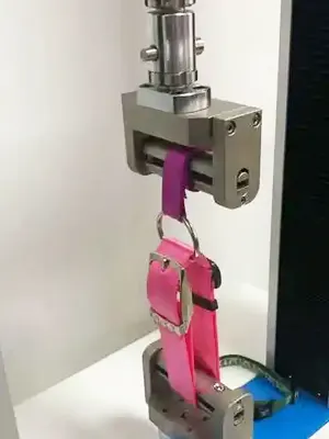
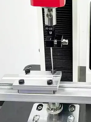
Use tensile grips, peel fixtures or purpose-built adapters to apply a controlled load to films, tapes, flexible laminates, bonded coupons and small assemblies. Suitability depends on the specimen geometry, surface, expected force, required angle and the result defined by the procedure.
Define the material and gripping section
Provide width, thickness, gauge length, bonded area, backing stiffness, surface condition and expected failure mode.
Confirm grip faces, angle and alignment
Review jaw type, clamping pressure, peel angle, adapter interface, available travel and whether specimen slip must be detected.
Configure the actual procedure
ASTM D903 may be reviewed for comparative peel or stripping tests. ASTM D1002 applies specifically to metal-to-metal single-lap adhesive joints. Confirm the current edition, specimen and speed before configuring the test.
Send the material, specimen drawing or dimensions, gripping section, applicable method, expected working and break loads, required results, test frequency and destination country. Include whether tensile, compression, bend, peel or multiple test types are required.Request a Benchtop UTM Configuration Review
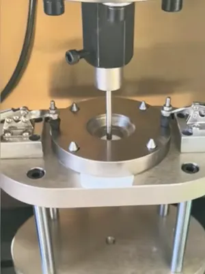
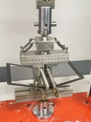
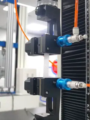
How do I choose the force capacity and usable test space for a benchtop tensile testing machine?
Choose the machine from the specimen, required results and test procedure—not from maximum frame capacity alone. The selected configuration must measure the lowest and highest required forces while providing enough space for the grips, specimen and expected extension.
FORCE RANGE
Define the Working, Peak and Lowest Reportable Forces
Provide the routine working load, estimated peak or break load and the lowest force that must be reported. Confirm which force transducer and verified working range cover those results; do not size the system from the frame’s maximum rated capacity alone.
USABLE TEST SPACE
Check Grip Separation, Fixture Height and Required Travel
State the specimen’s overall length, gauge length, gripping-section dimensions and expected extension or compression. Add the installed height of the grips or fixtures, then confirm initial separation, crosshead travel and loading access for the complete setup.
COMPLETE CONFIGURATION
Review the Load Train, Measurement and Procedure
The grips, adapters and fixtures must suit the material, geometry, surface and intended load. Also define test speed or control mode, strain measurement, stop conditions, calculations and report fields required by the current procedure.
What should you send for a configuration review?
Send the material, applicable method, specimen drawing or dimensions, gripping section, routine and estimated break loads, required results, expected extension, test frequency and destination country.
What materials and test types can a benchtop universal testing machine support?
A benchtop UTM should be selected from the specimen, procedure and required result—not from the material name alone. A suitable system may support films, plastics, rubber, textiles, adhesives, wire, thin metal and small components, but each application requires its own load range, test space, grips, fixtures and measurement method.
SPECIMEN
Define Material and Geometry
Provide material, thickness, width, diameter, gauge length, gripping section, surface condition and expected failure mode. Flexible film, soft rubber, wire and rigid components do not use the same gripping solution.
TEST MODE
Match the Required Loading Method
Identify whether the procedure requires tension, compression, three-point or four-point bending, 90° or 180° peel, shear, puncture or another fixture-defined test.
CONFIGURATION
Confirm Measurement and Space
Check expected force, lowest reportable force, travel, speed, direct strain measurement, fixture height, calculations and report fields for the current procedure.
How should force accuracy and the usable measurement range be specified?
Do not judge measurement capability from machine size or one headline accuracy percentage. The useful question is whether the proposed force transducer and its verified range cover both the lowest and highest forces required by your specimens and procedure.
FRAME RATING
Maximum Capacity Is Not the Working Range
Frame capacity indicates the machine limit; it does not prove that small forces can be measured with the required uncertainty or resolution.
FORCE CHANNEL
Select the Load Cell from Expected Results
State the routine force, expected peak or break force and lowest force that must be reported. Delicate and stronger specimens may require different force transducers on the same frame.
VERIFICATION
Confirm Range, Class and Documentation
Identify the applicable verification procedure, required class or acceptance criteria, verification points, units and documentation. Review the current edition and laboratory requirements before ordering.
Request a Force-Measurement Review
Send expected force ranges, specimen types and the governing procedure so the load cell and verification requirements can be reviewed.
What bench space, power and site conditions are required for installation?
Benchtop does not mean that every laboratory bench or outlet is automatically suitable. Confirm the complete installed envelope, machine mass, working access and utilities before delivery—especially for extra-height frames and large fixtures.
SPACE
Installed Envelope and Access
Check footprint, total height, rear and side clearance, crosshead travel, doorways, lifting route and operator access. Include the installed height of grips, fixtures and protective devices.
SUPPORT
Bench Capacity and Stability
Confirm that the bench is level, rigid and rated for the machine, fixtures and applied reactions. Avoid a location exposed to excessive vibration or unstable support.
UTILITIES
Power, Computer and Environment
Verify electrical supply, grounding, computer location, cable routing and the temperature or humidity conditions required by the proposed system and procedure.
SAFETY
Working Area and Training
Define specimen-fragment risk, guarding needs, emergency access and safe clearance. Operators should be trained for specimen installation, method setup, limits and emergency procedures.
Can one benchtop UTM perform tensile, compression, bend and peel tests?
Often yes—provided the frame, load cell, travel, speed, fixtures, measurement channels and software are suitable for every required procedure. Changing a fixture expands capability, but it does not by itself establish method compliance.
TENSION AND PEEL
Grips, Alignment and Travel
Tensile and peel work may require different jaw faces, grip pressure, peel angle, travel and break detection. Flexible specimens also need enough travel after initial grip separation.
COMPRESSION
Platens and Available Height
Compression requires rated platens or application-specific fixtures, suitable alignment, clear height and deformation measurement for the required result.
BEND TESTING
Span and Fixture Geometry
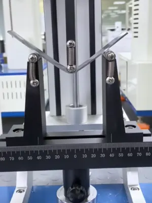
Confirm support span, loading-nose and support radii, specimen dimensions, fixture capacity and deflection measurement for three-point or four-point bending.
How do grips and fixtures affect test suitability and repeatability?
Grips and fixtures define how load enters the specimen. A frame with adequate force capacity can still produce unusable results when the jaw face, clamping pressure, alignment, fixture rating or available test space is wrong.
SPECIMEN INTERFACE
Match Geometry and Surface
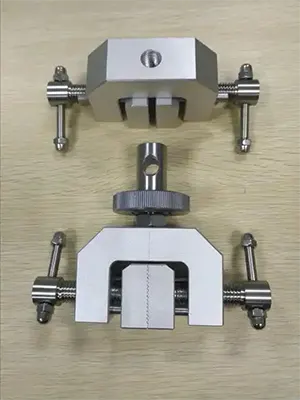
Provide thickness, width or diameter, gripping length, surface condition, stiffness and expected failure mode. Smooth film, soft elastomer, wire, rigid plastic and finished components need different interfaces.
LOAD PATH
Control Slip, Damage and Bending
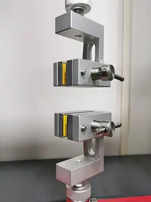
Select jaw faces and clamping force that hold the specimen without premature jaw breaks or local crushing. Keep adapters and fixtures aligned with the loading axis.
RATING AND SPACE
Review the Complete Assembly
Confirm grip and fixture load ratings, opening range, body height, mass, adapter thread and remaining test space at the required start position and travel.
Request a Grip and Fixture Review
Send a specimen drawing or clear photos, dimensions, surface details, expected load and test method for configuration review.
When is an extensometer required instead of crosshead displacement?
Crosshead displacement records movement of the machine system, including deformation or seating in the frame, grips and specimen. An extensometer measures deformation over a defined specimen gauge length and is normally required when the procedure calls for direct strain-based results.
CROSSHEAD DISPLACEMENT
Useful for machine movement, separation, travel limits and procedures that permit this measurement basis. It can include compliance, seating and grip movement, so it should not automatically be treated as specimen strain.
EXTENSOMETER
Use when the method or required result depends on direct gauge-length strain, such as modulus, yield or proof stress, specified elongation or strain control. Select gauge length, strain range, contact force and travel for the specimen.
What software, calculations and report fields should be confirmed before ordering?
Software should be reviewed against the actual test procedure and laboratory workflow. Do not assume that every calculation, control mode or report format is included simply because the system displays a force–displacement curve.
METHOD CONTROL
Define the Test Sequence
List preload, control mode, speed or rate, limits, hold steps, cycling needs, break detection, return behavior and stop conditions.
RESULTS
Specify Calculations and Validity Checks
Identify required strength, stress, strain, modulus, yield or proof values, peel averages, compression results, specimen corrections and any acceptance rules.
REPORTING
Confirm Fields and Data Export
List specimen identifiers, dimensions, units, curve display, operator fields, batch summaries, templates, raw-data needs and export formats.
INTEGRATION
Review Interfaces Before Ordering
Confirm computer requirements, user permissions, external devices and any data or system integration that is genuinely required.
Request a Method and Reporting Review
Send the current procedure and a sample report showing the fields, calculations and output format your laboratory needs.
Should I choose a single-column or dual-column benchtop testing machine?
Choose from load, stiffness, fixture size, specimen travel and laboratory space—not from column count alone. Both formats can be useful when correctly configured, but they serve different working envelopes.
SINGLE-COLUMN FRAME
Often practical for lower-force work, compact benches and easy side access. Confirm that its load rating, stiffness, travel, throat depth and fixture space cover the largest intended setup.
DUAL-COLUMN FRAME
May provide greater load capacity, stiffness and usable width for larger grips, bend fixtures or components. It can also require more bench area, height and installation capacity.
What information should I send for an accurate benchtop UTM configuration and quotation?
A useful quotation should define a complete test system, not only a frame model. Provide the information below so the load frame, force transducer, grips, fixtures, strain measurement, software and installation requirements can be reviewed together.
SPECIMEN
Material and Geometry
Send material, drawing or dimensions, gripping section, surface condition, gauge length, orientation and expected failure mode. Add photos for finished parts or irregular specimens.
PROCEDURE
Method and Required Results
Identify the current standard or internal procedure, test type, speed or control mode, required calculations, acceptance rules and report fields.
LOAD AND TRAVEL
Working Range and Test Space
State routine and maximum expected loads, lowest reportable force, expected extension or compression, fixture height and required travel.
SITE AND USE
Operation and Delivery Conditions
Provide test frequency, available power, bench or floor constraints, computer or integration needs and destination country.
Send Your Test Requirements
Attach specimen drawings, procedures and a sample report where available. DERUI can then review the configuration and identify any missing technical inputs before quotation.