We design and build a full range of universal testing machines (UTMs) and specialized lab equipment for rigorous quality control, research, and development.

Derui is a specialized manufacturer and supplier of material testing equipment.Our products serve quality control, research, and development needs
across industries like aerospace, automotive, and manufacturing.
Global Consultation Hotline:+86 15580327593

Controlled Temperature and Humidity Test Equipment

Environmental Test Chambers

Configure an environmental test chamber for controlled temperature, humidity, temperature cycling, thermal exposure or large-product testing. Start with the current test procedure, specimen and load, working volume, temperature and humidity conditions, change rate, heat load and facility requirements—not with chamber volume alone.

Define the exposure before selecting the chamber

01 · TEST PROFILE

Identify the current procedure, temperature and humidity setpoints, ramps, dwells, cycles, duration, tolerances and whether the specimen operates during exposure.

02 · SPECIMEN AND WORKSPACE

Provide specimen dimensions, quantity, mass, arrangement, heat dissipation, electrical load, required shelves, ports and usable working-volume needs.

03 · PERFORMANCE AND SITE

Confirm range, change rate, uniformity or fluctuation requirements, control and recording, electrical power, water, heat rejection, access, floor loading and safety provisions.

Send the complete environmental profile for a configuration review.

Include the procedure and edition, specimen and load details, workspace, temperature and humidity profile, change-rate basis, heat load, monitoring points, utilities, installation access and destination country.

Send Chamber Requirements →

Environmental Chamber Selection

Choose an Environmental Test Chamber by Test Profile and Workspace Requirements

Compare temperature and humidity chambers, temperature test chambers, walk-in chambers and thermal shock configurations by the exposure profile, usable workspace, specimen load, temperature and humidity conditions, change-rate requirement, monitoring method and facility constraints. Review each product page for its verified operating range and configuration, then send the complete test procedure and specimen details for final selection.

Chamber Type Comparison

Compare Environmental Test Chamber Types

The correct chamber type depends on how the exposure must be produced—not simply on chamber volume. Match the required temperature and humidity profile, specimen size and heat load, transition method and installation conditions before comparing individual models.

01

Controlled Hot and Cold Exposure

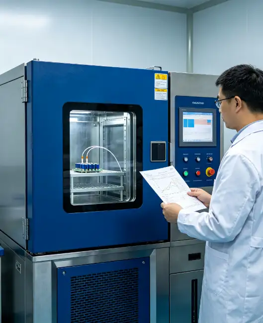
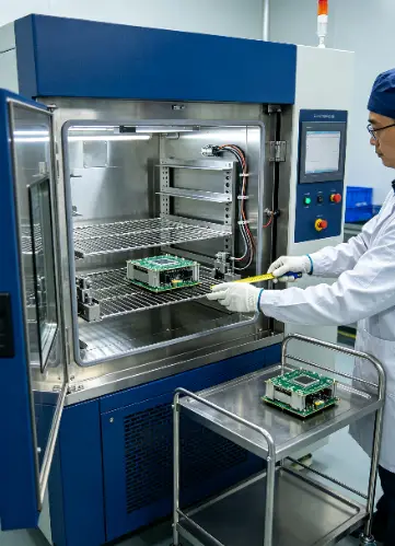
Temperature Test Chambers

Use a temperature chamber when the method requires controlled hot, cold, dwell or temperature-cycling exposure and relative-humidity control is not part of the test.

Confirm: operating range, change-rate definition, specimen heat load, working volume, airflow, monitoring points and recovery after loading.
02

Combined Climatic Exposure

Temperature and Humidity Chambers

Use this configuration when the procedure specifies controlled temperature and relative humidity together for steady-state, cyclic or conditioning exposure.

Confirm: the achievable temperature–humidity envelope, condensation or non-condensation intent, water requirements, load effects, sensor location and stabilization criteria.

03

Large Specimens and Batch Loads

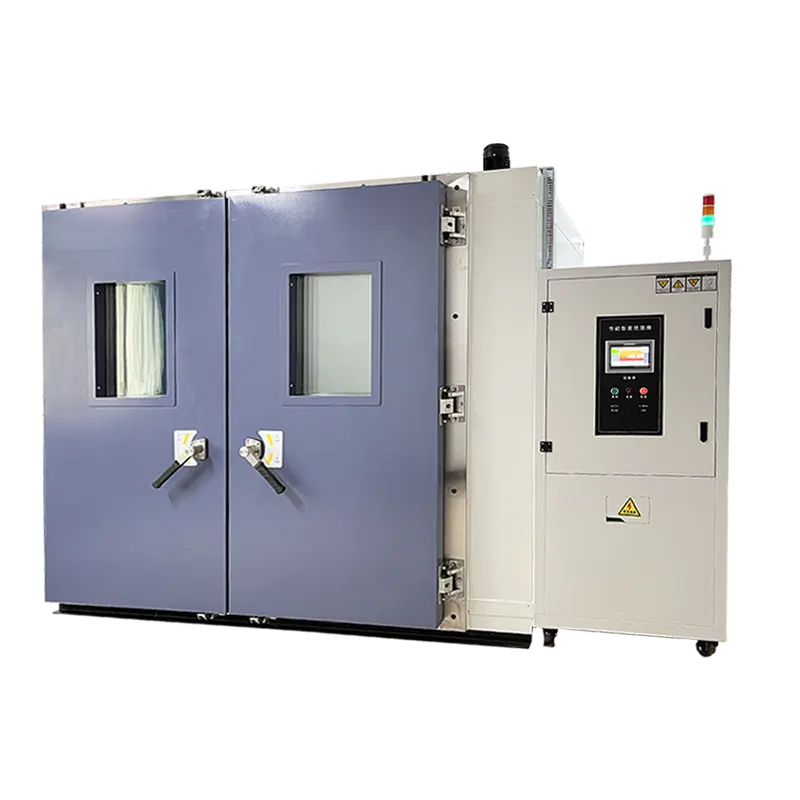
Walk-In Environmental Chambers

Use a walk-in chamber when assembled products, large test articles or batch quantities cannot be accommodated in a reach-in workspace.

Confirm: usable internal dimensions, door and installation access, floor loading, total heat and moisture load, airflow clearance, utilities and room heat rejection.

04

Abrupt Hot-to-Cold Transfer

Thermal Shock Chambers

Use a thermal shock chamber when the method requires the specimen to move or switch rapidly between separately conditioned hot and cold environments.

Confirm: two-zone or three-zone arrangement, specimen mass and basket size, transfer time, exposure time, recovery criteria, cycle count and monitoring method.

Important distinction: a rapid temperature change inside one chamber is not automatically equivalent to thermal shock between separately conditioned zones. Use the terminology and exposure sequence defined by the current test procedure.

Not sure which chamber architecture matches the procedure?

Send the procedure and edition, exposure profile, specimen dimensions and mass, powered heat load, required workspace, monitoring points, utilities and installation constraints.

Request a Chamber Review →
How to Choose an Environmental Test Chamber

Choose the chamber from the required exposure profile, specimen and facility conditions—not from chamber volume or headline temperature range alone. Use these five checks to define the method, workspace, environmental performance, control and installation requirements before requesting a configuration.

  • Test Method & Exposure Profile
  • Specimen, Load & Workspace
  • Environmental Performance
  • Control, Monitoring & Records
  • Facility, Verification & Support

Start with the current test procedure and complete exposure sequence. A setpoint alone does not define the chamber, control method or acceptance criteria.

01 · PROCEDURE

Identify the Governing Method

Provide the standard, customer specification or internal procedure, its edition and the exact method or section that applies.

02 · SEQUENCE

Define Every Exposure Step

List temperature and humidity setpoints, ramps, dwells, cycles, duration, transitions and whether the specimen operates during exposure.

03 · ACCEPTANCE

Separate Exposure from Evaluation

Define conditioning tolerances, stabilization criteria, specimen monitoring, functional checks and the records required to judge the test.

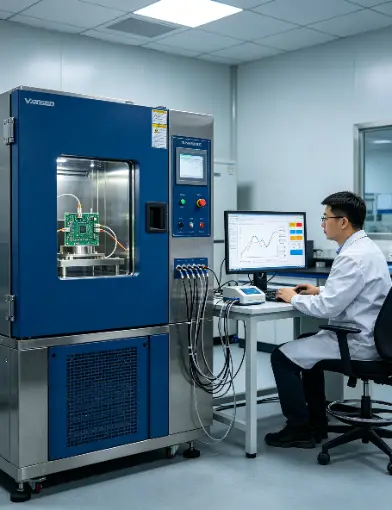
Engineer configuring a programmed temperature and humidity exposure profile on an environmental test chamber
Equipment Definition

What Is an Environmental Test Chamber?

An environmental test chamber is an enclosed test system that creates controlled conditions around a specimen for a defined period or sequence. Depending on its configuration, it may provide temperature exposure, temperature and humidity conditioning, programmed cycling, large-workspace exposure or rapid transfer between separately conditioned hot and cold zones.

The chamber is one part of the test method. The procedure, specimen and load, sensor locations, control settings, stabilization criteria, monitoring equipment and evaluation requirements determine what the exposure means and what can be reported.

Core Chamber Functions

01 · WORKSPACE

Enclosure and Air Circulation

The insulated workspace, shelves, ports and air-circulation arrangement establish the controlled space around the installed specimen.

02 · CONDITIONING

Heating, Cooling and Humidity

The configured conditioning system generates the required temperature and, where provided, humidity conditions within its verified operating envelope.

03 · CONTROL

Program, Sensors and Limits

The controller uses chamber sensors to regulate setpoints, ramps, dwells and cycles while configured limits and alarms protect the test setup.

04 · EVIDENCE

Monitoring and Test Records

Configured records may document chamber conditions, program steps, events and alarms; separate sensors are used when specimen temperature or function must be measured.

What the Test Can Document or Evaluate

EXPOSURE RECORD

Chamber Air Conditions and Time

The configured system may record programmed and measured chamber temperature, humidity where applicable, exposure time, cycle status, events and alarms. Reported fields depend on the controller and recording configuration.

SPECIMEN MONITORING

Product Temperature and Operation

Additional sensors and functional channels can document specimen temperatures, powered operation or other defined responses. Chamber air temperature should not be reported as specimen temperature without suitable measurement.

POST-EXPOSURE EVALUATION

Condition Against Acceptance Criteria

Inspection, dimensional checks, electrical or functional tests and other evaluations determine whether the specimen meets the documented acceptance criteria after or during exposure.

An environmental exposure does not predict service life by itself

Results apply to the documented procedure, chamber configuration, specimen and load, sensor locations, exposure profile and evaluation method. An accelerated exposure represents real service time only when the governing method or a validated acceleration model establishes that relationship.

  • How Does an Environmental Test Chamber Work?
Controlled Exposure Workflow

How Does an Environmental Test Chamber Work?

The chamber conditions the air around a specimen according to a documented program while configured sensors provide control and monitoring feedback. The complete workflow links the test method, load arrangement, environmental sequence and evaluation criteria.

1

Confirm the Test Method and Exposure Profile

Identify the current procedure and edition, required temperature and humidity points, ramps, dwells, cycles, duration, tolerances, stabilization criteria and acceptance checks.

2

Prepare and Load the Specimen

Condition or inspect the specimen as required, record its initial state and arrange it with suitable supports, spacing, airflow clearance, cables, ports and services. Include powered heat and moisture loads in the setup.

3

Install the Required Monitoring Sensors

Place independent air or specimen sensors at the locations required by the method or laboratory plan. Confirm identification, attachment, cable routing, measurement range and data acquisition before closing the chamber.

4

Program the Sequence, Limits and Events

Enter the ordered setpoints, transition instructions, dwell timing, cycle count and supported specimen power events. Configure relevant alarms and safety limits, then review the program before starting.

5

Run, Stabilize and Monitor the Exposure

The conditioning system heats, cools and—when configured—humidifies or dehumidifies the circulating air. Begin dwell timing according to the procedure's stabilization definition, while monitoring chamber conditions, specimen channels, events and alarms.

6

Evaluate the Specimen and Report the Test

Record the completed exposure, deviations and interruptions, then inspect or functionally test the specimen using the defined criteria. Report the chamber, configuration, load, sensors, actual conditions and evaluation results needed for traceability.

Measurement boundary: The chamber controller regulates conditions at its control sensor. If product temperature, internal component temperature or functional response is required, those values need suitable specimen sensors and separate measurement channels.
Application Scope

Environmental Test Chamber Applications and Validation Goals

Environmental exposure is most useful when the procedure, specimen configuration and acceptance criteria are defined before testing. Match the chamber and monitoring setup to the engineering question—not to an industry label alone.

01
PRODUCT RELIABILITY

Verify Operation Across Defined Environmental Conditions

Define: Operating and non-operating states, exposure profile, powered heat load, monitoring channels and pass/fail criteria.

Evaluate: Functional interruptions, parameter drift, visible damage and post-exposure performance under the documented conditions.

02
ELECTRONICS AND ELECTRICAL

Assess Components, Assemblies and Enclosures

Define: Board or assembly configuration, electrical load, cable routing, condensation intent, functional measurements and sensor locations.

Evaluate: Startup and operation, insulation or connection issues, intermittent faults and changes found during or after exposure.

03
AUTOMOTIVE AND INDUSTRIAL COMPONENTS

Condition Parts and Subassemblies Before Evaluation

Define: Installed orientation, fluids or electrical services, operating state, transition sequence, fixture and follow-on test requirements.

Evaluate: Leakage, deformation, sealing, electrical or mechanical function and condition after the specified environmental sequence.

04
MATERIALS, SEALS AND BONDS

Condition Materials for Comparative Testing

Define: Material construction, surface preparation, conditioning duration, support method and the mechanical, dimensional or visual test performed afterward.

Evaluate: Comparative changes in dimensions, appearance, flexibility, adhesion, sealing or mechanical properties using separate specified measurements.

05
PACKAGING AND STORAGE CONDITIONING

Condition Packages Before Distribution or Material Tests

Define: Package and contents, conditioning atmosphere and duration, stacking arrangement, airflow, moisture load and subsequent drop, vibration or compression test.

Evaluate: Package condition and the results of the separate follow-on test; conditioning alone does not establish distribution performance.

06
LARGE OR BATCH LOADS

Expose Assemblies or Multiple Specimens in a Walk-In Chamber

Define: Total dimensions, mass, quantity, heat and moisture load, placement, access, floor requirements and representative monitoring locations.

Evaluate: Conditions at specified points and the response of representative specimens, with load arrangement and measurement locations documented.

Planning a new environmental validation program?

Send the procedure, specimen and load, exposure profile, operating state, monitoring points, acceptance criteria, workspace and installation conditions.

Discuss the Test Application →
Environmental Test Chambers FAQ

How do I choose the right type of environmental test chamber?

Choose the chamber from the exposure method, specimen and load—not from a generic chamber name or volume alone. First determine whether the test requires temperature only, combined temperature and humidity, a large walk-in workspace or rapid transfer between separately conditioned hot and cold environments.

01

TEMPERATURE EXPOSURE

Choose a Temperature Test Chamber for Controlled Hot and Cold Conditions

Use this type when the procedure specifies hot, cold, dwell or temperature-cycling exposure without controlled relative humidity. Confirm the required operating points, heating and cooling-rate basis, specimen heat load, usable workspace, airflow and monitoring locations.

02

TEMPERATURE AND HUMIDITY

Choose a Climatic Chamber for Combined Temperature and Relative Humidity

Use a temperature and humidity chamber when both conditions must be controlled together for steady-state, cyclic or conditioning exposure. Check every required point against the model's achievable temperature–humidity envelope and define condensation intent, water supply, load effects and stabilization criteria.

03

LARGE OR BATCH LOADS

Choose a Walk-In Chamber for Large Assemblies or Multiple Specimens

Use a walk-in configuration when the specimen or batch cannot fit a reach-in workspace. Define usable internal dimensions, total mass, heat and moisture load, placement, door and delivery access, floor loading, utilities, heat rejection and representative monitoring points.

04

ABRUPT HOT-TO-COLD TRANSFER

Choose a Thermal Shock Chamber When the Method Requires Separate Hot and Cold Zones

Use this architecture when the specimen must transfer rapidly between separately conditioned environments. Confirm the required zone arrangement, specimen and basket size, transfer and exposure times, recovery criteria, cycle count and monitoring method. Do not treat rapid cycling in one chamber as automatically equivalent.

What should you send for a chamber-type review?

Send the test procedure and edition, complete exposure profile, specimen dimensions, mass and quantity, powered heat and moisture load, required workspace, monitoring points, condensation intent, available utilities, installation access and destination country.

Request an Environmental Chamber Review →

What installation, maintenance and operator training are required?

Requirements depend on chamber type and configuration. Before delivery, confirm the installation route, floor and service clearances, electrical and fluid utilities, heat rejection, environmental limits, routine maintenance access and the responsibilities of the supplier and site team.

01

INSTALLATION

Prepare Access, Utilities and Heat Rejection

Confirm doorway and route dimensions, final footprint, floor loading, leveling, power, grounding, water and drainage where required, room ventilation or cooling, exhaust and service clearance.

02

MAINTENANCE

Follow the Model-Specific Inspection Schedule

Typical work may include cleaning the workspace, condenser or filters, checking water and drainage systems, door seals, sensors, alarms, electrical connections and refrigeration condition. Use the delivered manual and service plan.

03

TRAINING

Cover Setup, Limits, Alarms and Records

Operators should understand loading and airflow, program creation, sensor use, condensation risks, alarm response, emergency procedures, data export and the difference between chamber conditions and specimen measurements.

Review Installation and Handover Scope

Send site photos or drawings, utilities, access route, operating schedule, documentation needs and the personnel who require training.

Contact DERUI →

What factors affect environmental chamber energy and utility consumption?

Consumption varies with chamber size, insulation, refrigeration and humidity configuration, ambient conditions, setpoints, transition rate, specimen load, door openings and operating schedule. It should be estimated from the proposed model and duty cycle—not from a universal percentage claim.

01

TEST DEMAND

Profile, Load and Door Activity

Extreme setpoints, rapid transitions, powered heat loads, frequent door openings and long humidity operation can increase energy or water demand and recovery time.

02

SYSTEM AND SITE

Configuration and Ambient Conditions

Workspace size, conditioning technology, cooling method, heat rejection, room temperature, ventilation, water quality and maintenance condition influence utility use.

03

COMPARISON BASIS

Request a Defined Operating Scenario

Compare proposed systems using the same profile, load, ambient condition and operating hours. Ask which utilities are included, how consumption is estimated and which options change the result.

Do not publish a fixed energy-saving percentage, annual consumption or operating-cost figure unless it is supported by a stated model, test cycle, utilities and calculation basis.

How can environmental chamber performance be verified before delivery?

Agree on the verification and acceptance scope before ordering. The plan should identify the purchased configuration, test points, load condition, measurement locations, reference instruments, stabilization rules, acceptance criteria and documents to be delivered.

01

FACTORY CHECK

Define Functional and Performance Tests

List safety checks, controller functions, alarms, temperature and humidity points, transitions and any mapped conditions that must be demonstrated at the factory. State whether testing is empty or uses a representative load.

02

MEASUREMENT PLAN

Agree on Sensors, Locations and Criteria

Specify reference instruments, calibration status, mapped points, recording interval, stabilization, calculation method, uncertainty treatment and permitted deviations.

03

DELIVERY EVIDENCE

List Reports and Configuration Records

Require equipment identification, configuration, test setup, raw or summarized readings, deviations, results and applicable calibration or verification certificates. Define any site acceptance separately.

Define the Acceptance Plan Before Ordering

Send the required performance points, test method, load condition, mapped locations, criteria and document list so they can be reviewed with the quotation.

Contact DERUI →

What information is required for an accurate environmental chamber quotation?

An accurate quotation must define the chamber, test method, specimen load, monitoring, facility and acceptance scope. A model name or internal volume alone is not enough to price a configuration or confirm technical suitability.

01

METHOD AND PROFILE

Send the Complete Exposure Requirement

Provide the procedure and edition, temperature and humidity points, ramps, dwells, cycles, duration, tolerances, stabilization, condensation intent and operating or storage state.

02

SPECIMEN AND LOAD

Define Workspace and Conditioning Demand

Send specimen dimensions, mass, quantity, arrangement, fixtures, powered heat load, moisture load, required ports, shelves, cables and representative sensor locations.

03

CONTROL AND EVIDENCE

Specify Monitoring and Documentation

List program functions, alarms, independent channels, specimen measurements, data export, report fields, access requirements and calibration or verification documents.

04

SITE AND DELIVERY

Provide Utilities, Access and Acceptance Scope

State power, water, drainage, heat rejection, ambient conditions, floor loading, doorway and route, installation responsibility, destination country, commissioning, training and factory or site acceptance requirements.

Send Your Environmental Chamber Requirements

Attach the test procedure, exposure table, specimen drawing, utility information and required acceptance documents. Delivery schedule can then be evaluated for the confirmed configuration.

Contact DERUI →

What temperature and humidity range can an environmental chamber achieve?

The answer depends on the specific chamber, humidity system, load and test condition. A published temperature range and a published humidity range do not mean that every combination of those values is simultaneously achievable.

01

TEMPERATURE RANGE

Check Every Required Hot and Cold Point

List the minimum and maximum temperatures, intermediate dwells, transition sequence, load condition and duration. Verify operation at each point rather than relying on one overall range statement.

02

HUMIDITY ENVELOPE

Review Temperature and Relative Humidity Together

Humidity capability is normally limited to a defined temperature–humidity envelope. Confirm every required combination, water quality, condensation intent, stabilization criterion and whether the specimen adds heat or moisture.

03

SPECIAL CONDITIONS

Use Purpose-Built Equipment for Pressure or Other Variables

Altitude or low-pressure testing, solar exposure, corrosive atmospheres and other variables require specifically designed systems. Do not infer these capabilities from a standard temperature or humidity chamber.

Request the verified operating envelope and stated test conditions for the proposed model. Category-level wording cannot replace model-specific performance data.

How do I determine the required chamber workspace and specimen capacity?

Size the chamber from the complete installed load—not from nominal volume alone. The specimen, shelves, fixtures, airflow clearance, sensor locations, cables and access requirements must fit within the usable workspace without obstructing the configured air path.

01

SPECIMEN ENVELOPE

Define the Largest Installed Load

Provide the maximum L × W × H, mass, quantity, orientation and any support frame or fixture. Include cables, hoses, moving parts and the space required to load, inspect or operate the specimen.

02

USABLE WORKSPACE

Allow for Airflow, Shelves and Sensors

Confirm internal dimensions and usable shelf area after allowing for circulation, wall clearance, ports, sensors and manufacturer loading restrictions. Nominal chamber volume does not establish usable specimen capacity.

03

LOAD ARRANGEMENT

Document Placement and Representative Points

Define how single or multiple specimens will be arranged, whether they are representative of routine loads and where chamber-air and specimen sensors will be located for the required evaluation.

Review the Complete Chamber Load

Send specimen drawings, quantity, mass, arrangement, fixture and shelf requirements, cable or hose access and the required monitoring locations.

Contact DERUI →

How do specimen heat load and moisture load affect chamber selection?

A powered or moisture-releasing specimen changes the conditioning demand inside the workspace. These loads can affect achievable temperature and humidity conditions, change rate, recovery time, stability and the required refrigeration, heating, humidification or dehumidification configuration.

01

POWERED HEAT

Calculate the Maximum Heat Dissipation

State normal, peak and time-dependent electrical power converted to heat inside the chamber. Include power supplies, lamps, motors, batteries, auxiliary equipment and duty cycles located in the workspace.

02

MOISTURE LOAD

Identify Water Release or Absorption

Describe wet products, open liquids, porous materials, packaging, evaporation, condensation intent and any process that adds or removes moisture. Confirm drainage and water-handling requirements where applicable.

03

OPERATING PROFILE

Review Load and Environment Together

Provide the complete temperature and humidity sequence, powered states, transitions and dwell periods. Chamber suitability should be verified at the required load and operating points, not inferred from an empty-chamber headline rating.

Do not place an energized or moisture-releasing specimen in the chamber until electrical, condensation, material and safety risks have been reviewed for the specific configuration.

How should environmental chamber heating and cooling rates be specified?

Define the required rate together with its calculation method and load condition. “Fast change” can refer to an average rate across a broad interval, a linear rate through a defined segment or the actual specimen response, and these are not equivalent.

01

RATE DEFINITION

State the Temperature Interval and Calculation Basis

Specify the start and end temperatures, average or linear requirement, allowed deviations, ramp direction and whether overshoot or settling time is included. Use the conventions required by the current procedure.

02

LOAD CONDITION

Confirm Empty-Chamber or Loaded Performance

Provide specimen and fixture mass, material, powered heat load and arrangement. A chamber rate measured empty may not represent the air or specimen rate with the actual load installed.

03

AIR VERSUS SPECIMEN

Separate Chamber-Air and Product Temperature

If the specimen must follow a defined rate, identify sensor locations and stabilization or lag limits. The chamber control sensor cannot establish internal product temperature without suitable specimen measurement.

Send the Complete Transition Requirement

Include the procedure, temperature interval, calculation basis, load details, required air and specimen rates, tolerances and dwell criteria.

Contact DERUI →

What is the difference between temperature fluctuation, uniformity and accuracy?

These terms describe different measurement questions and should not be treated as interchangeable. Definitions, sensor locations, time intervals, load condition and reference-instrument uncertainty must be stated before comparing chamber specifications or acceptance results.

01

FLUCTUATION

Variation at One Point Over Time

Fluctuation describes how the measured condition changes with time at a defined location after the chamber reaches the specified state. Confirm the calculation interval, parameter and operating condition.

02

UNIFORMITY

Difference Among Locations in the Workspace

Uniformity or spatial variation compares conditions at multiple defined points. Results depend on workspace size, sensor arrangement, setpoint, airflow, empty or loaded condition and the selected calculation method.

03

ACCURACY AND UNCERTAINTY

Compare Indication with a Reference

Accuracy claims require a defined measurand, reference instrument, calibration status, method and uncertainty. Controller resolution or sensor display increments alone do not establish chamber accuracy.

Use the terminology and calculation method required by the applicable procedure or agreed acceptance plan; similar words may be defined differently in different documents.
telephonetelephone

hotline:
155 8032 7593

WhapsAppWhapsApp
WhapsApp
LinkedinLinkedin
Linkedin
messagemessage

Contact us to provide you with exclusive service!