We design and build a full range of universal testing machines (UTMs) and specialized lab equipment for rigorous quality control, research, and development.

Derui is a specialized manufacturer and supplier of material testing equipment.Our products serve quality control, research, and development needs
across industries like aerospace, automotive, and manufacturing.
Global Consultation Hotline:+86 15580327593

Mechanical and Dynamic Test Equipment

Vibration Testing Machines and Systems

Compare vibration testing machines for packaging transport simulation, controlled sine or random excitation, high-frequency testing and other documented vibration profiles. The correct system is defined by the test method, specimen and fixture mass, frequency range, displacement, velocity, acceleration, force and control requirements—not by a model name alone.

Define the test before selecting the system

01 · TEST PROFILE

Identify the current procedure and whether the required input is fixed-displacement transport vibration, sine, random, shock or another defined profile.

02 · TEST ARTICLE

Provide specimen dimensions and mass together with fixture, head-expander or table requirements and the intended test direction.

03 · SYSTEM ENVELOPE

Confirm frequency, displacement, velocity, acceleration, force or payload, controller channels, facility utilities and safety requirements.

Need to translate a vibration specification into a system configuration?

Send the procedure and edition, test profile, specimen and fixture mass, mounting dimensions, frequency range, displacement, velocity, acceleration, required test direction, controller channels, facility utilities and destination country.

Send Test Requirements →

System Selection

Choose a Vibration Test System by Test Type and Performance Requirements


Start with the required vibration profile and test article—not with maximum force or frequency alone. Compare each system by supported test type, specimen and fixture mass, frequency range, displacement, velocity, acceleration, force or payload, test direction, controller and facility requirements. Open the product page for its verified performance envelope before requesting a configuration.

System Type Comparison

Compare Vibration Test System Types


The correct vibration testing machine depends first on the required input motion and test objective. Mechanical, electrodynamic and servo-hydraulic systems use different drive and control principles; one type should not be assumed to reproduce every vibration profile.

Use the current procedure and the complete performance envelope—not one headline specification—to compare systems.

01

Packaging and Repetitive Shock

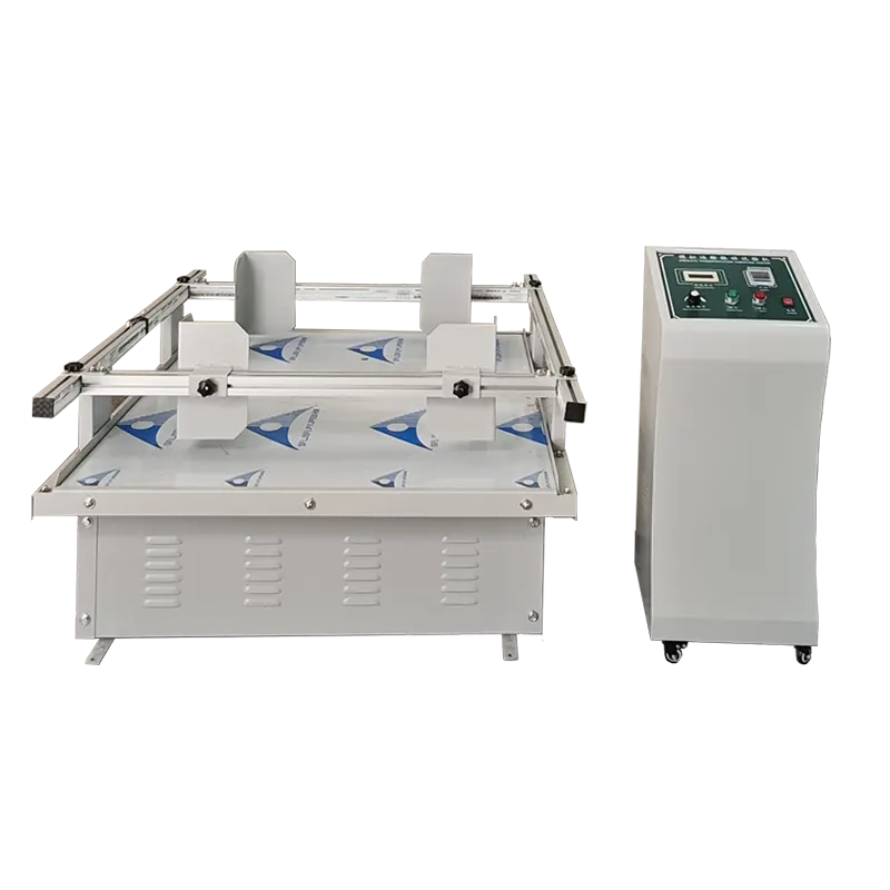
Mechanical Transport Simulation Table

Best suited to: packaged-product fixed-displacement vibration or repetitive-shock procedures when supported by the machine configuration.

Verify: drive motion, table size, rated package load, fixed displacement, CPM or Hz range, restraint method, timer and procedure compatibility. It is not a substitute for controlled random vibration.

02

Controlled Dynamic Excitation

Electrodynamic / High-Frequency Shaker System

Best suited to: controlled sine, random or compatible shock profiles for components and assemblies when the shaker, amplifier and controller are rated for the requested test.

Verify: separate sine, random and shock force ratings; frequency, displacement, velocity and acceleration limits; moving mass, payload, fixture, test direction, controller channels and cooling.

03

Low Frequency and Large Motion

Servo-Hydraulic Vibration System

Best suited to: low-frequency, high-force or large-displacement dynamic loading of heavy specimens and structures when supported by a fatigue-rated actuator and load train.

Verify: dynamic force, frequency, stroke, velocity, waveform and amplitude limits; servo valve, hydraulic power supply, controller, fixtures, sensors, floor loading, utilities and safety provisions.

Select by the required profile—not by the technology name alone.

Send the procedure, specimen and fixture mass, mounting dimensions, frequency range, displacement, velocity, acceleration, force or payload, direction and controller requirements for review.

How to Choose a Vibration Test System

Choose the system from the required vibration profile, test article and facility conditions—not from maximum frequency or force alone. Use these five checks to define the motion, payload, controller, measurement and verification requirements before requesting a configuration.

  • Test Profile
  • Test Article & Fixture
  • Motion & Performance
  • Control & Measurement
  • Site, Verification & Delivery

Start with the required test profile—not with a shaker technology. A transport simulation table, electrodynamic shaker and servo-hydraulic system create different motion and are not interchangeable.

01 · PURPOSE

Define What Must Be Reproduced

State whether the goal is package transport simulation, resonance search, sine dwell, random vibration, repetitive shock, durability cycling or another defined procedure.

02 · PROCEDURE

Confirm the Current Test Method

Provide the applicable ASTM, IEC, ISO, ISTA, MIL-STD, customer or internal procedure, its edition and the exact method or profile to be performed.

03 · PROFILE

Send the Actual Profile Values

List frequency, displacement, velocity, acceleration, duration, sweep or spectrum details, tolerances, control strategy and required test directions.

  • What is a Vibration Test System?
Equipment definition

What Is a Vibration Test System?

A vibration test system applies a defined mechanical motion to a package, product, component or assembly under controlled laboratory conditions. Depending on the selected technology, it may reproduce repetitive transport motion, controlled sine vibration, random vibration, shock-compatible profiles or low-frequency high-displacement loading.

The complete system is more than the vibration generator. It includes the drive source, moving table or interface, fixture, controller or operating controls, sensors and—when required—data acquisition. The applicable test procedure and verified system configuration determine what can actually be performed and reported.

Core System Components

01 · EXCITER

Drive and Vibration Source

Mechanical, electrodynamic or servo-hydraulic hardware generates the required motion within its rated envelope.

02 · INTERFACE

Table, Slip Table and Fixture

The mounting interface transfers motion to the specimen and supports the required direction and load.

03 · CONTROL

Controller or Operating Controls

Controls define speed, frequency, profile, duration, limits and sequencing supported by the configured system.

04 · MEASUREMENT

Sensors and Data Acquisition

Accelerometers and acquisition channels are required when motion or specimen response must be controlled, measured or recorded.

What the System Can Measure or Document

MECHANICAL TRANSPORT SIMULATION

Table Motion and Package Response

May document operating frequency or cycles per minute, fixed displacement or table motion, exposure time and observed package or product condition. It should not be described as controlled random vibration unless the actual system provides that capability.

ELECTRODYNAMIC SHAKER

Controlled Motion and Dynamic Response

When equipped with the required controller and sensors, the system can control and record acceleration profiles and may measure response, resonance or transmissibility. Supported sine, random and shock modes must be confirmed from the configured ratings.

SERVO-HYDRAULIC SYSTEM

Low-Frequency High-Force Motion

A suitably rated dynamic system may control and record force, displacement, velocity or acceleration for low-frequency, high-force or large-displacement tests. Capability depends on the actuator, servo valve, controller, sensors and hydraulic power unit.

A vibration result applies to the documented test conditions

Results must be interpreted with the test procedure, specimen and fixture, mounting direction, profile, controller settings, sensor locations, tolerances, duration and inspection criteria. A vibration exposure alone does not prove performance under drop, impact, compression, climatic or every real distribution condition.

  • How Does a Vibration Test System Work?
Operating workflow

How Does a Vibration Test System Work?

A vibration test system applies a documented motion profile to a specimen under controlled laboratory conditions. The exact workflow depends on the system type, but the sequence is always defined by the test profile, mounting method, control mode, measurement chain and pass/fail criteria.

Transport simulation tables, electrodynamic shakers and servo-hydraulic systems all follow the same logic: prepare the article, configure the envelope, run the profile, monitor the response and document the result against the procedure.

1

Define the vibration profile and the test article

Start with the specimen, the failure mode you are trying to evaluate and the required profile. Record the product mass, fixture mass, mounting direction, frequency range, acceleration or displacement target, duration and any standards or customer method that govern the test.

2

Mount the specimen with the required fixture

Secure the device under test, package or assembly to the table, slip table or other interface using a fixture that matches the actual geometry and loading direction. A correct fixture preserves the intended response instead of introducing unwanted resonance, looseness or secondary motion.

3

Configure the right control mode and system envelope

Select the control strategy that fits the system type and test objective, then confirm the usable frequency, displacement, velocity or force range. For transport simulation, that may mean table motion and repeatability; for electrodynamic shakers, sine, random or shock control; for servo-hydraulic systems, low-frequency high-force or large-displacement motion.

4

Run the vibration sequence and monitor response

Execute the programmed profile while the controller and sensors track the actual response. Depending on the setup, the system may record acceleration, displacement, force, transmissibility or other response channels and stop automatically if the defined limits are reached.

5

Review the data and document the result

Compare the recorded response with the acceptance criteria, then document the specimen condition, operating settings, sensor locations and any observed damage or performance change. The final result should always be tied back to the documented method, sample, fixture and operating envelope rather than the machine name alone.

The result only applies to the documented vibration conditions

A vibration result is valid only for the stated specimen, fixture, profile, duration, control mode and measurement setup. If you need to compare system types or size the correct platform, start with the test article and the required profile, then request a configuration review.

Send Vibration Requirements →

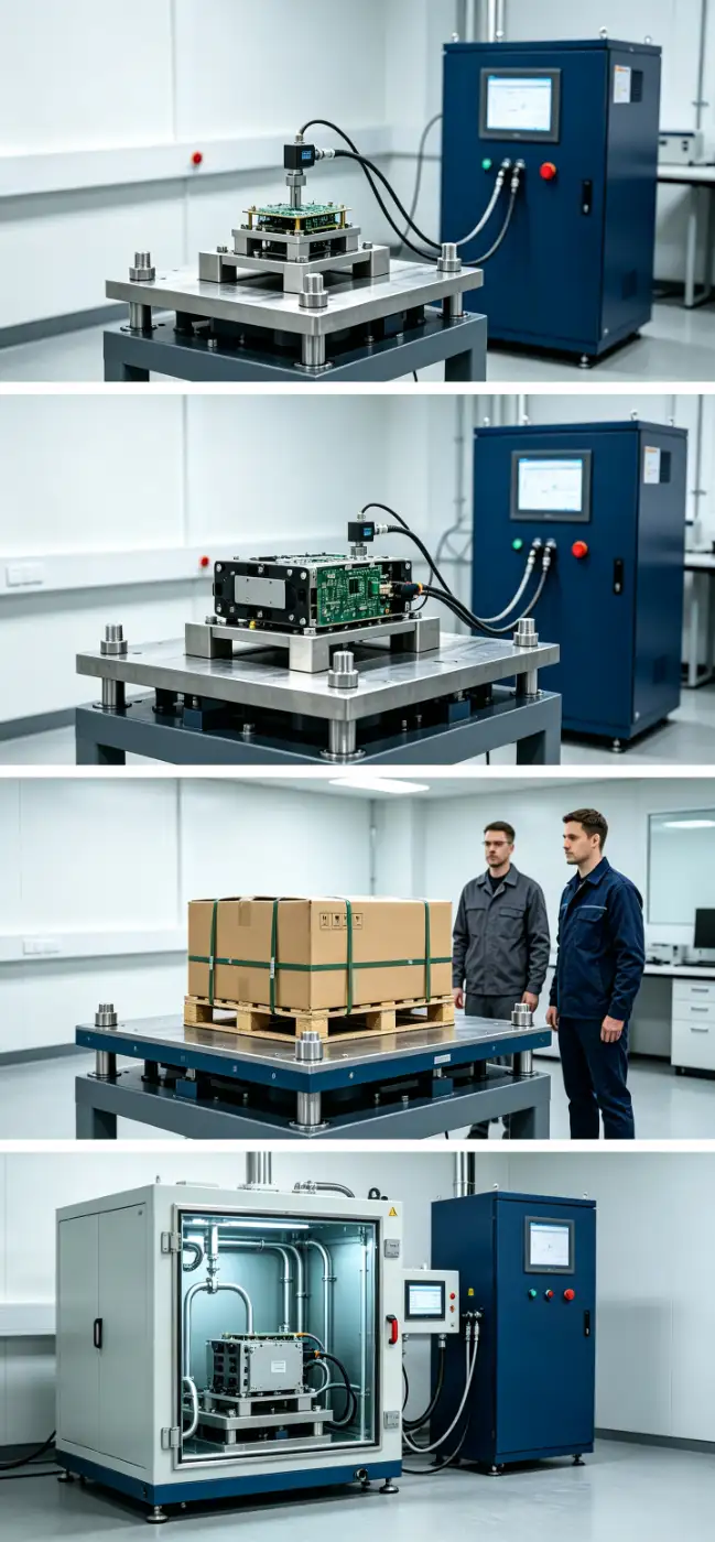
Vibration testing applications include resonance identification, random vibration, transport simulation and combined vibration-temperature testing. System capabilities depend on the configured shaker, controller, fixture, sensors and environmental chamber.

Vibration Test Applications: From Transport Simulation to Dynamic Validation

Different vibration systems answer different engineering questions. Match the test objective, specimen and required motion profile to the correct platform before comparing frequency, displacement, acceleration, force or payload ratings.

01
Dynamic behaviour

Locate Resonances and Evaluate Vibration Endurance

Use a controlled sine sweep to identify resonant frequencies, then apply a documented dwell or endurance profile where the procedure requires it. The system must provide suitable frequency, force, displacement and closed-loop control for the combined specimen and fixture.

02
Durability evaluation

Reproduce Defined Random Vibration Profiles

Apply a specified power spectral density profile to assess structural integrity, connections and functional performance under broadband excitation. Duration should follow the governing method or a justified acceleration model; it should not automatically be treated as an equivalent number of service years.

03
Distribution testing

Evaluate Packaged Products for Transport Vibration

Use fixed-displacement, repetitive-shock or random vibration methods according to the selected packaging procedure. Table motion, payload, restraints and sequence depend on the packaged product and the applicable ISTA, ASTM or customer-defined method.

04
Combined environments

Combine Vibration with Controlled Temperature Conditions

Where simultaneous stresses are required, a compatible shaker can be integrated with a climatic chamber. Confirm chamber access, thermal range, fixture design, sealing, cooling, sensors and controller compatibility as part of the complete configuration.

Which vibration application do you need to reproduce?

Send the specimen and fixture mass, dimensions, test direction, profile type, frequency range, displacement, velocity, acceleration or force requirement, duration, procedure and installation conditions.

Request an Application Review →

Vibration Test Systems FAQ

Still unsure which system is right for your validation challenges? Our engineering team specializes in translating product requirements into precise test specifications.

How is the required force rating calculated for an electrodynamic shaker?

Use F = m × a only as the starting estimate. A valid shaker selection must include every moving mass and then check the complete sine, random or shock profile against the system’s applicable force, displacement, velocity, acceleration and frequency limits.

01

TOTAL MOVING MASS

Include More Than the Test Article

Include the specimen, fixture, adapters, head expander or slip-table components that move during the test, together with the shaker armature or other moving elements required by the manufacturer’s sizing method.

02

PROFILE AND UNITS

Match Mass and Acceleration to the Test Mode

For a sine profile, use the required peak acceleration with consistent units. Random and shock sizing require the actual spectrum or pulse, duration and bandwidth; a single GRMS or peak-g value does not describe every limiting condition.

03

PERFORMANCE ENVELOPE

Check More Than the Headline Force Rating

Compare the complete loaded profile with the proposed system curves and separate sine, random and shock ratings. Confirm low-frequency displacement, velocity, acceleration, thermal limits, test direction and any manufacturer derating before selection.

Request a Shaker Sizing Review

Send the complete profile plus the specimen, fixture and moving-interface masses. DERUI can identify the inputs needed for a loaded performance review.

Contact DERUI →

Can one vibration system perform sine, random and classical shock tests?

Sometimes—but the presence of a digital controller does not prove that the shaker, amplifier and mechanical interfaces can reproduce every requested profile. Each mode must fit within the verified operating envelope of the complete loaded system.

01

CONTROL CAPABILITY

Confirm the Required Waveforms and Channels

Identify sine sweep or dwell, random PSD, classical shock pulse and any combined-mode requirements. Confirm controller software, input channels, control strategy, abort limits, data recording and licensing for the actual methods.

02

MODE-SPECIFIC RATINGS

Review Sine, Random and Shock Separately

Check the applicable force rating, frequency, displacement, velocity, acceleration and duration for each waveform. Shock performance may be limited by pulse shape, duration, payload and available displacement even when sine and random profiles fit.

03

LOADED CONFIGURATION

Evaluate the Complete Moving Assembly

Include the specimen, fixture, armature, head expander, slip table and other moving components. Verify the mounting direction, cooling, amplifier and mechanical interfaces for every profile rather than assuming one bare-table rating covers all tests.

A system should be described as suitable only for the documented profiles that remain inside its verified loaded performance envelope.

Why do fixture design and accelerometer placement matter in vibration testing?

The fixture and measurement points determine how commanded motion reaches the test article. Excess mass, insufficient stiffness, loose joints, poor geometry or an unsuitable control location can distort the profile and make the recorded result difficult to interpret.

01

FIXTURE DYNAMICS

Control Mass, Stiffness and Resonance

Design the fixture for the specimen, direction, frequency range and force level. Review material, joints, fasteners, mounting pattern, natural frequencies and cross-axis response instead of assuming the stiffest or lightest-looking design is adequate.

02

LOAD TRANSFER

Mount the Specimen Without Unintended Motion

The fixture should transmit the required motion while limiting looseness, rocking, distortion and local damage at mounting points. Torque, contact surfaces and installation sequence should be documented and repeated.

03

MEASUREMENT POINTS

Separate Control and Response Objectives

Place control accelerometers according to the procedure and control strategy; use response sensors where product behavior must be measured. Confirm orientation, attachment method, cable routing, mass loading, channel range and calibration status.

Request a Fixture and Sensor Review

Send specimen and fixture drawings, mounting pattern, mass, center of gravity, test axes, frequency range and proposed sensor locations.

Contact DERUI →

What information is required for an accurate vibration system configuration and quotation?

An accurate quotation must define the complete system—not only a shaker or table model. Provide the information below so the vibration source, amplifier or drive, controller, table interfaces, fixture, sensors, cooling, installation and acceptance scope can be reviewed together.

01

TEST ARTICLE

Specimen, Fixture and Mounting

Send specimen and fixture masses, dimensions, center of gravity, mounting drawing, table-interface requirement, test directions and any head expander, slip table, restraint or environmental-chamber requirement.

02

TEST PROFILE

Method and Motion Requirements

Provide the current procedure and every required sine, random, shock or transport profile with frequency, displacement, velocity, acceleration, force or payload, duration, axes, tolerances and sequence.

03

CONTROL AND DATA

Measurement and Reporting Scope

List control and response channels, accelerometers, sensor locations, functional monitoring, abort limits, data acquisition, software methods, export formats and required report fields.

04

SITE AND DELIVERY

Utilities, Installation and Acceptance

State available electrical power, cooling, compressed air or hydraulic utilities, floor loading, room access, noise or exhaust constraints, destination country, installation scope, training needs, acceptance tests and required calibration or verification documents.

Send Your Vibration Test Requirements

Attach the test procedure, profile files, specimen and fixture drawings, site utility information and a sample report where available. DERUI can then identify missing inputs before issuing a technical configuration.

Contact DERUI →

Which standards and test procedures should be defined before selecting a vibration system?

Start with the exact procedure and current edition, then extract the required profiles and acceptance conditions. A machine name or broad statement of “compliance” does not prove that the proposed configuration can perform every method within IEC, ISO, ASTM, ISTA, MIL-STD or a customer specification.

01

DOCUMENT

Identify the Exact Procedure and Edition

Provide the standard, method, procedure number, edition, test category and any customer amendments. Different procedures under the same standards family can specify different specimens, axes, severities, durations and reporting.

02

PROFILE

Extract the Required Motion and Sequence

List sine, random, shock, repetitive-shock or other profiles; frequency range; PSD or acceleration levels; displacement; velocity; pulse shape; duration; axes; tolerances; control strategy and sequence.

03

ACCEPTANCE

Define Instrumentation and Pass/Fail Criteria

State required control and response channels, sensor locations, pre- and post-test checks, functional monitoring, abort limits, inspection criteria, data retention and report fields.

Send the Current Test Procedure

Attach the relevant method pages or customer specification so the system envelope, controller, sensors, fixtures and documentation can be reviewed together.

Contact DERUI →

Can a vibration test system operate vertically, horizontally or on multiple axes?

A test can be performed in more than one direction, but vertical, horizontal and simultaneous multi-axis operation are not the same configuration. Rotating the specimen or adding a slip table normally enables sequential single-axis tests; it does not automatically create a coordinated multi-axis system.

01

VERTICAL AXIS

Use the Armature Interface for Vertical Excitation

Confirm table size, mounting pattern, payload support, fixture height, center of gravity and access. The loaded vertical profile must remain within force, displacement, velocity and acceleration limits.

02

HORIZONTAL AXIS

Use a Compatible Slip Table or Reorient the Article

A trunnion and slip table may support horizontal excitation on suitable electrodynamic systems. Review bearing and drive-bar mass, alignment, lubrication or utilities, floor space and the reduced loaded performance of the horizontal configuration.

03

MULTI-AXIS TESTING

Define Sequential or Simultaneous Motion

Sequential testing applies each axis separately by reorientation or different interfaces. Simultaneous multi-axis testing requires purpose-built actuators, tables, controls, sensors and coordination; upgrade feasibility must be evaluated from the original system architecture.

Do not promise a future multi-axis upgrade until the required degrees of freedom, phase relationship, payload, envelope, controls and facility have been defined.

Which type of vibration test system is suitable for my application?

Choose the system from the required vibration profile, test article, fixture and test direction—not from a technology name or maximum rating alone. Transport simulation tables, electrodynamic shakers and servo-hydraulic systems operate in different frequency, motion and load ranges and are not interchangeable by default.

01

PACKAGED-PRODUCT TESTING

Use a Transport Simulation System for Distribution Vibration

Choose this route when the test article is a package, shipping container or unit load and the procedure specifies fixed-displacement, repetitive-shock or random transport vibration. Confirm the exact motion type, table size, payload, restraint method, test duration and current ISTA, ASTM or customer procedure before selecting the equipment.

02

CONTROLLED DYNAMIC EXCITATION

Use an Electrodynamic Shaker for Defined Sine, Random or Shock Profiles

An electrodynamic system is commonly considered for components and assemblies requiring controlled sine, random or compatible classical-shock testing. Verify the separate force ratings for each mode together with total moving mass, frequency, displacement, velocity, acceleration, fixture, controller, cooling and vertical or horizontal test requirements.

03

LOW-FREQUENCY HIGH-LOAD MOTION

Use a Servo-Hydraulic System for Heavy or Large-Displacement Tests

A servo-hydraulic configuration may be appropriate for heavy specimens, structures and low-frequency tests requiring high dynamic force or large displacement. Review actuator force, usable stroke, velocity, waveform, frequency, load train, hydraulic power supply, cooling, foundation, sensors, controls and safety requirements as one system.

What should you send for a system-type review?

Send the procedure and edition, specimen and fixture mass, dimensions, mounting interface, test direction, profile type, frequency range, displacement, velocity, acceleration, force or payload requirement, duration, controller channels, available utilities and destination country.

Request a Vibration System Review →

How do frequency, displacement, velocity and acceleration limits affect shaker selection?

These limits describe different parts of the vibration system’s usable motion envelope. A test can remain below maximum frequency and force yet still exceed the available displacement, velocity or acceleration at another point in the profile.

01

LOW FREQUENCY

Check Required Displacement

Low-frequency motion often requires greater travel to reach the specified acceleration. Confirm whether displacement is stated as peak, peak-to-peak or another convention, and compare it with the system’s usable rating for the selected mode.

02

MID-RANGE MOTION

Check Velocity and Continuous Operation

Velocity can become the limiting factor between the displacement-controlled and acceleration-controlled regions. Review peak or RMS conventions, profile duration, cooling and any reduced-field or duty-cycle conditions.

03

HIGH FREQUENCY

Check Acceleration, Force and Fixture Response

At higher frequencies, available acceleration and force may limit the loaded test. Fixture resonance, control stability, sensor mounting and the specimen response must also be considered; the published maximum frequency alone does not establish suitability.

Review the Complete Motion Profile

Send the frequency breakpoints and required displacement, velocity, acceleration and force values with their units and peak, RMS or peak-to-peak conventions.

Contact DERUI →

How do specimen mass, fixture mass and test direction affect system capacity?

The shaker moves a complete assembly, not the specimen alone. Added mass, fixture dynamics, mounting interface, center of gravity and test direction can reduce usable acceleration or introduce loads that are not visible in a simple payload figure.

01

MOVING MASS

Account for Every Moving Component

Record the specimen, fixture, adapters, fasteners, head expander, slip-table drive components and other moving masses required by the proposed setup. Use these values in the manufacturer’s loaded performance review.

02

GEOMETRY AND MOMENTS

Define Size, Center of Gravity and Overhang

Provide overall dimensions, mounting pattern, center-of-gravity location and any offset or overhang. A tall or eccentric article can create overturning moments and cross-axis forces even when its mass is below the nominal payload.

03

TEST DIRECTION

Review Vertical and Horizontal Setups Separately

State every required axis and whether the specimen can be reoriented. Vertical armature, horizontal slip table and purpose-built multi-axis configurations have different moving interfaces, support conditions and usable performance.

Provide a drawing of the specimen and proposed fixture assembly. Mass alone is not enough to approve the mounting or test direction.

Can vibration testing be combined with temperature or humidity exposure?

It can be done when the shaker, climatic chamber, interfaces, fixtures, sensors and controls are designed to operate together. Combined testing is an engineered configuration—not a default capability of every vibration system or environmental chamber.

01

MECHANICAL INTERFACE

Confirm Chamber Access and Shaker Connection

Review chamber opening, table or armature interface, thermal barrier, flexible sealing, fixture height, specimen access and relative movement. The connection must preserve the required motion without compromising the chamber environment.

02

OPERATING ENVELOPE

Check Temperature, Humidity and Vibration Together

Define temperature and humidity ranges, transition rates, dwell periods, vibration profile, duration and simultaneous sequence. Verify cooling, heat transfer, condensation control and any derating of the shaker, sensors or fixtures.

03

CONTROL AND SAFETY

Coordinate Sensors, Cables and Protection

Confirm accelerometer and cable temperature ratings, feedthroughs, chamber sensors, control channels, interlocks, abort limits, grounding and emergency procedures. Document which system controls each part of the combined sequence.

Suitability must be confirmed for the exact chamber, shaker and procedure. Do not infer combined-test capability from either machine’s standalone specification.
telephonetelephone

hotline:
155 8032 7593

WhapsAppWhapsApp
WhapsApp
LinkedinLinkedin
Linkedin
messagemessage

Contact us to provide you with exclusive service!