




What Is a Small
Tensile Testing Machine?
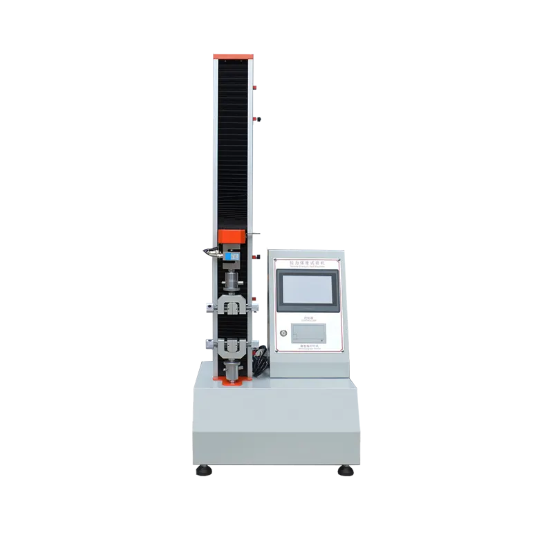
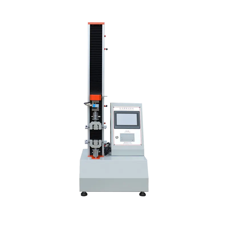
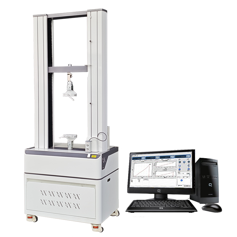
A small tensile testing machine is a compact electromechanical test system used to apply a controlled load and record force and crosshead movement on low-force specimens or components. The DERUI DR-L201-1 is currently listed with a nominal 5 kg load cell and is intended to be configured around the actual specimen, grip, test speed, travel and required result.
Quick answer: choose this model only when the complete expected force range fits the configured load measurement range and the specimen, both grips and required extension fit the usable test space.
Is This Low-Force Tester
the Right Starting Point?
“Small” describes the system format, not universal suitability. Start with the expected force and specimen, then review the complete configuration.
Potentially suitable
- Low-force tensile tests on thin films, light textiles, threads, fibres or small polymer specimens.
- Peel, pull-off or component force tests when the required fixture and software method are available.
- Routine quality-control comparisons using a controlled specimen and repeatable internal procedure.
- Laboratories that need a compact frame but can provide a stable bench and sufficient working height.
Review another configuration when
- The highest expected force approaches or exceeds the configured 5 kg load range.
- Large, stiff or long specimens and heavy grips consume the available force or test space.
- The method requires a separate extensometer, strain control or environmental chamber not confirmed for this model.
- Compression, bending or another test mode is required but its fixture, space and software procedure have not been verified.
Six Inputs That Define a Small Tensile Testing Machine
A model number alone cannot confirm a valid test. Provide these inputs so the load cell, frame, grips, movement and result calculation can be reviewed together.
Material and specimen
Identify the material or component, thickness, width, overall length, gripping section, surface and expected failure behaviour.
Method and revision
Provide the current ISO, ASTM, EN, customer or internal procedure. The method controls specimen preparation, rate, sequence and calculation.
Minimum and maximum force
State the lowest result that must be measured, normal working force and expected break force—not only the highest value.
Grips and test space
Define the gripping surfaces, initial jaw separation, specimen installation clearance and expected extension after loading.
Required results
List force, extension, tensile strength, elongation, peel strength or other report fields and how each value must be calculated.
Workflow and documentation
State batch size, tests per day, data export, report format, destination-country power and required verification documents.
Best inquiry package: specimen photo or drawing + method + expected force + extension + required result.
Reliable Data Comes From the Complete Test Chain
The machine records force and crosshead movement. A reportable material property also depends on specimen dimensions, alignment, gripping, strain measurement, method settings and calculation rules.
Use the correct load range
Confirm accuracy and resolution across the forces actually measured. A nominal maximum capacity does not define the useful lower measurement limit.
Prevent slip and grip breaks
Jaw face, clamping method and alignment must suit the specimen without crushing, cutting or allowing movement in the grips.
Separate travel from test space
Stroke is not the same as usable grip separation. Load cell, adapters and grips consume space before the specimen is installed.
Define how extension is measured
Crosshead movement can support some force-extension workflows. Modulus or method-defined strain may require a separate extensometer and compatible software.
Important: the published load accuracy, speed and stroke describe the machine configuration. They do not by themselves prove compliance with every tensile, peel or component test method.
Installation, Operation and Maintenance
At approximately 68 kg, this model should be treated as bench-installed equipment rather than a portable hand-carried tester. Follow the supplied manual and ordered configuration.
Prepare the location
- Use a level bench with adequate load capacity and low vibration.
- Allow working height and clearance for the frame, grips and specimen loading.
- Confirm the ordered power supply; the current page lists single-phase AC 220 V.
Control each test
- Use the correct specimen preparation, conditioning and test procedure.
- Set travel limits before loading and keep hands outside the active load path.
- Check specimen alignment and stop if slipping, grip damage or abnormal noise occurs.
Maintain traceability
- Inspect grips, adapters, cables and moving parts at defined intervals.
- Protect method files and record configuration changes in the laboratory system.
- Arrange force verification and service according to the quality system, use and applicable requirements.
Small Tensile Testing Machine FAQs
These answers define the configuration questions for DR-L201-1 without replacing the current test procedure or final model review.
01What is the capacity of the DR-L201-1 small tensile testing machine?
The current product page lists a nominal 5 kg load cell and a published test-force range of 1 g to 5 kg. Confirm the usable verified range and required safety margin against both the lowest and highest expected forces before ordering.
02Can this machine calculate tensile strength and elongation?
It can record force and machine movement through its configured control system. Tensile strength also requires valid specimen dimensions, while method-defined elongation, strain or modulus may require a suitable extensometer and calculation procedure. Confirm the required outputs before quotation.
03Which materials can be tested?
Potential low-force applications include thin films, light textiles, threads, fibres, small polymer specimens, tapes and lightweight components. Suitability depends on the expected force, specimen geometry, grip, speed, travel and governing method—not the material name alone.
04Is the machine portable?
No portability claim should be made from its compact format. The current page lists an approximate machine weight of 68 kg, so plan a stable bench, safe handling and a fixed working position.
05Can it perform peel, compression or bending tests?
Additional test modes are possible only when the ordered frame, force range, usable space, fixture and software procedure support the applicable method. Provide each required test separately so compatibility can be confirmed.
06What should I send for a configuration review?
Send the material or component, specimen drawing, current method, expected minimum and maximum forces, starting grip separation, expected extension, results to report, daily volume, power supply and documentation requirements.
Confirm the Tester Against Your Real Specimen
Send the specimen, method, expected force and extension so the DR-L201-1 or an alternative configuration can be reviewed before quotation.