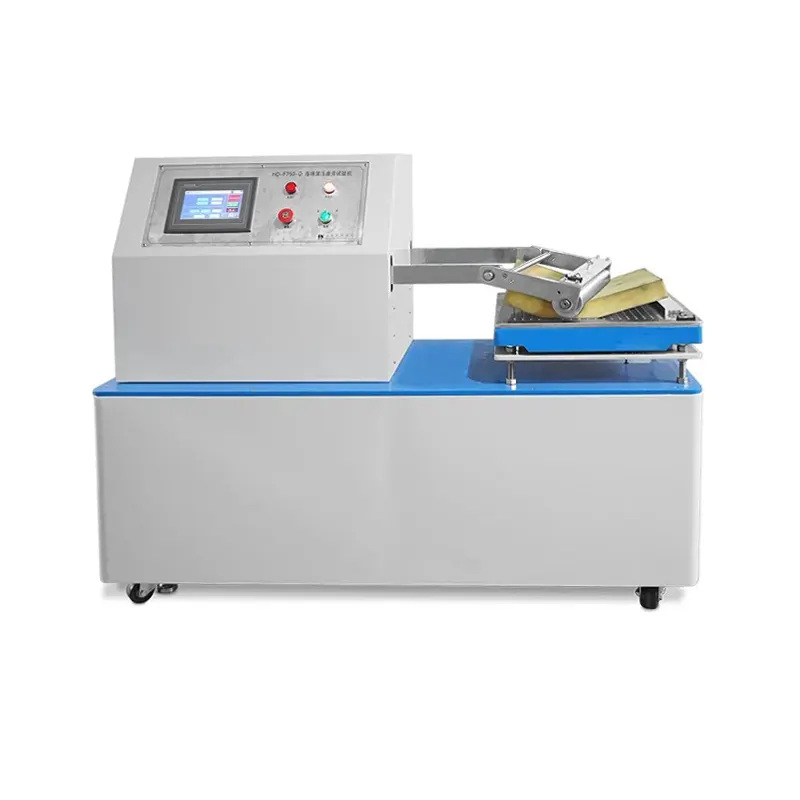


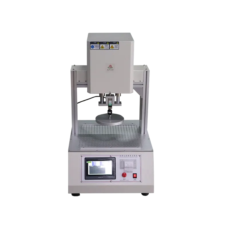
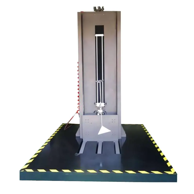
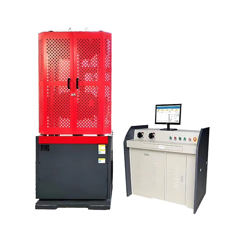
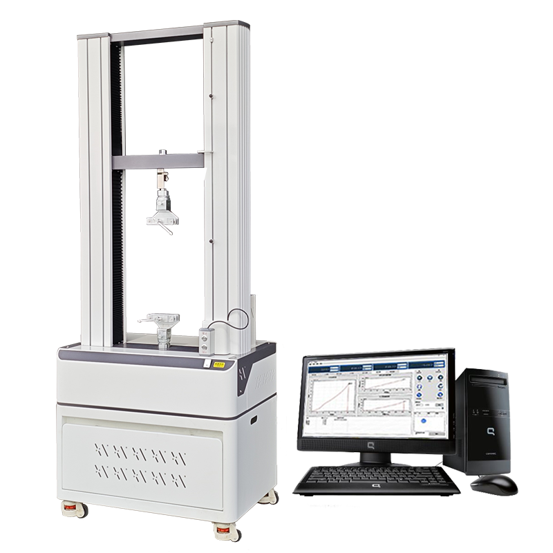

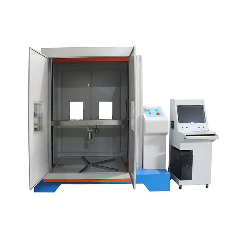
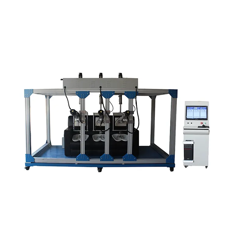

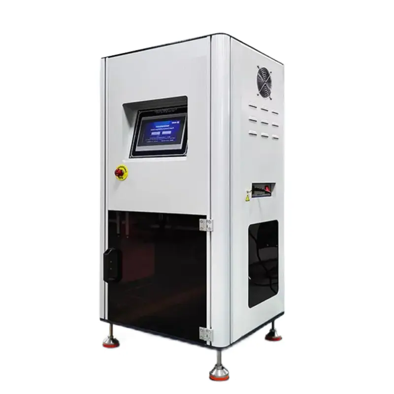
DR-J203 Foam Dynamic Fatigue Tester
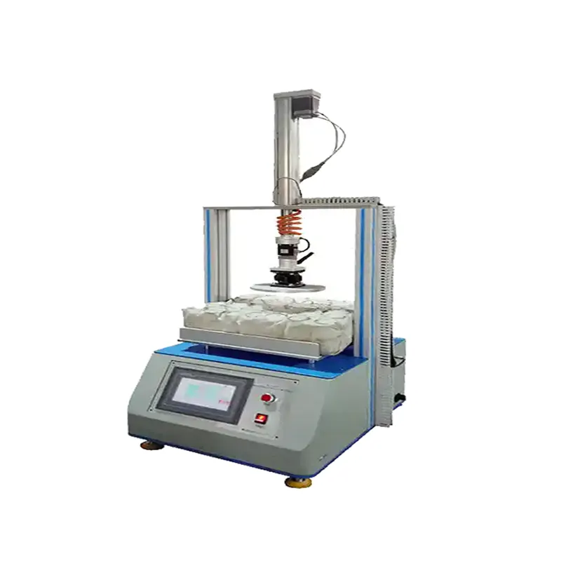
The DR-J203 repeatedly loads a flexible polyurethane foam specimen with a flat horizontal indenter under a defined constant-force pounding program. The complete method compares baseline and post-fatigue thickness, 40% IFD support and visible cellular breakdown.
Quick answer: this is a dedicated ASTM D3574 Test I3 pathway. The fatigue machine supplies the pounding exposure, while a valid result also requires controlled IFD/thickness measurements, recovery timing and one traceable specimen record before and after cycling.
How the Constant-Force Pounding Method Works
The specified flat indenter repeatedly compresses the specimen at the method force and rate. The machine does not replace the measurements required before and after the fatigue stage.
Condition specimen
Prepare, orient and condition the foam under the controlled method environment.
Measure baseline
Record initial thickness and 40% IFD/support value using the required measurement setup.
Apply pounding
Run the specified constant-force cycle program while recording cycles and abnormal stops.
Recover and remeasure
After the defined recovery interval, repeat thickness and IFD measurements and inspect damage.
Traceability rule: specimen ID, conditioning, initial values, force, rate, completed cycles, recovery time, final values and visible condition belong in one test record.
Three Outcomes Define the Fatigue Result
40% IFD loss
Compare indentation force support at the specified deflection before and after the pounding exposure.
Thickness loss
Compare controlled-load thickness values using the same measurement practice and stated recovery interval.
Structural breakdown
Inspect for cell collapse, cracking, splitting, crumbling or other visible damage against an unflexed reference.
Choose DR-J203 for Constant-Force Pounding
Do not select by the word “fatigue” alone. Match the apparatus to the procedure named in the specification.
DR-J203 · Test I3
Flat-indenter vertical pounding at constant force; strongest fit for the published 750 N / approximately 70 CPM pathway.
DR-J207 · Test I2
A loaded roller travels across restrained foam, adding lateral shear to compression.
DR-J202 · confirm method
The current product page lacks a verified fixed configuration; review it only after method and loading geometry are defined.
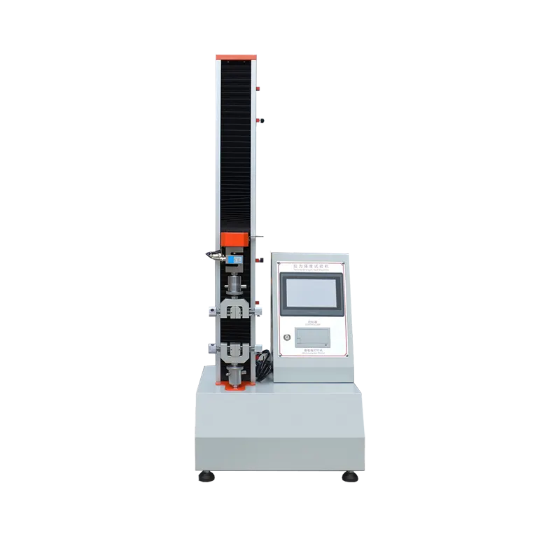
IFD measurement
Provides the pre/post support result; it is a companion measurement rather than the fatigue exposure itself.
Configure Test I3 Before Quotation
| Method element | Why it controls the result | DR-J203 review |
|---|---|---|
| Force and indenter | The vertical force and contact geometry define the compression exposure. | Confirm the applicable 750 N tolerance, indenter diameter/profile and alignment. |
| Rate and cycles | Procedure choice changes the number and pace of impacts and total test duration. | Confirm current edition, target CPM, program A/B/C where applicable and counter. |
| Specimen and support | Size, orientation, perforated support and conditioning affect airflow and deformation. | Provide specimen drawing, material, skin condition and preparation. |
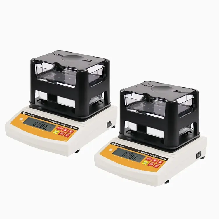
| Initial/final measurements | 40% IFD and thickness loss require a compatible force/thickness measurement system. | Define instrument, preload, locations, recovery interval and reporting fields. |
| Acceptance evidence | Static force verification alone does not prove cycle rate, counter or dynamic operation. | Agree force, geometry, rate, counter, safety and endurance checks for FAT. |
ISO boundary: ISO 3385 also addresses load-bearing foam fatigue, but its current procedure must be reviewed separately. Do not claim ISO and ASTM equivalence from similar machine motion.
Control the Main Sources of Invalid Results
Conditioning
Control foam age, temperature, humidity, dimensions, orientation and time since cutting.
Force application
Verify the complete loading assembly and confirm the required force at the specimen.
Indenter alignment
Keep the loading face parallel, centred and clear through the full stroke.
Cycle integrity
Record set/completed cycles, rate, pauses, overloads, power loss and abnormal stops.
Recovery interval
Start post-fatigue measurements only after the procedure’s specified recovery period.
Companion measurement
Use the same verified IFD/thickness system and settings before and after fatigue.
Build a Verifiable DR-J203 RFQ
Send the exact fatigue procedure plus the pre/post measurement requirement. A machine quotation without both parts is incomplete.
Method and decision
- ASTM/ISO edition and procedure
- Required outputs
- Acceptance limits
- Permitted deviations
Foam specimen
- Material and end use
- Dimensions and orientation
- Skin and preparation
- Conditioning requirement
Fatigue program
- Force and indenter
- Rate and cycle count
- Support platen
- Stop/alarm requirements
Measurement and documents
- IFD/thickness equipment
- Recovery and report fields
- FAT and verification
- Power, manuals and training
DR-J203 Dynamic Fatigue Tester FAQs
01What does the DR-J203 foam fatigue tester do?
02Which ASTM D3574 procedure is the primary target?
03Is DR-J203 the same as a roller-shear tester?
04Does the fatigue machine directly report IFD loss?
05Can ISO 3385 and ASTM D3574 results be treated as equivalent?
06What is needed for a DR-J203 proposal?
Define the complete Test I3 workflow: specimen + pounding + cycles + recovery + IFD/thickness + report.