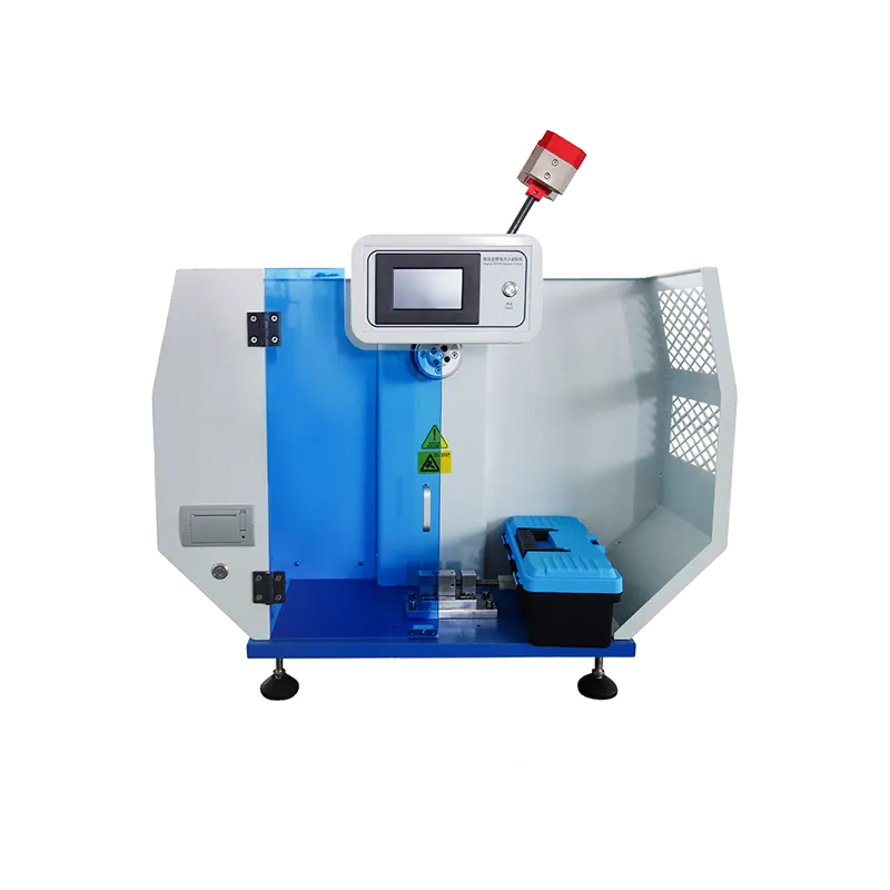



DR-C303 Digital Charpy Pendulum Impact Tester
The DR-C303 measures the fracture energy absorption and impact resistance of rigid plastics, reinforced composites, and engineering polymers under high-velocity three-point flexural impact. Designed for rigorous quality inspection and R&D formulation auditing according to ISO 179-1 and ASTM D6110.
Quick answer: Choose an impact tester by required standard (ISO 179 vs ASTM D6110), modular pendulum energy (0.5J to 50J), and specimen dimensions—not by maximum striking capacity alone. Verify automatic friction/air resistance compensation, optical encoder resolution, safety enclosure interlocks, and notch cutter availability before placing an order.
What Charpy Impact Energy Reveals About Polymers
Charpy Impact Strength (kJ/m²)
Calculated as absorbed kinetic energy divided by the residual cross-sectional area behind the notch. Serves as the primary industrial benchmark for plastic toughness and resistance to high-speed shock.
Ductile vs. Brittle Transition
Reveals how materials transition under temperature changes or notch stress concentration. Brittle fractures produce flat, clean surfaces with low absorbed energy; ductile fractures display yielding and stress whitening.
Fracture Type Classification
Standards require logging fracture type: Complete break (C), Hinge break (H), Partial break (P), or Non-break (N). Different failure modes cannot be directly averaged together in statistical QA reports.
Standard Operating Procedure for Reliable Charpy Data
Impact test repeatability depends on notch cutting radius, sample alignment centering, and friction compensation—not solely on the drop mechanism.
Precision Notch Preparation
Mill the 45° V-notch using a specialized motorized notch cutter. Maintain the tip notch radius (r = 0.25 mm ± 0.05 mm); worn blades create notch root tears that artificially lower impact strength.
Span Adjustment & Centering
Set anvil span distance (e.g., 62 mm for ISO 179-1 Type 1). Align the specimen horizontally using the centering notch guide so the striker strikes directly opposite the notch apex.
Friction Loss Tare Calibration
Execute an empty free-swing test prior to batch loading. The microcomputer automatically calculates windage and bearing drag, zeroing out tare energy before specimen testing.
Electromagnetic Release & Safe Capture
Trigger the electromagnetic lock via dual push-buttons or software inside the transparent interlocked safety shield. The pendulum drops freely and records rebound angle automatically.
Thermal Conditioning Notice: Impact toughness is highly temperature-dependent. Condition specimens at standard 23°C ± 2°C and 50% RH for at least 16 hours, or use a cryogenic chamber for low-temperature automotive ductility testing.
Standardized Test Methods & DR-C303 Compliance
| Standard | Scope & Geometry | DR-C303 Machine Configuration |
|---|---|---|
| ISO 179-1:2023 | Non-instrumented Charpy impact test on rigid plastics (edgewise and flatwise impact). | Striker radius 2.0 mm ± 0.5 mm, span 62 mm or 70 mm, impact velocity 2.9 m/s (≤5J) and 3.8 m/s (>5J). |
| ASTM D6110-24 | Standard Test Method for Determining the Charpy Impact Resistance of Notched Plastics. | Striker radius 0.8 mm ± 0.1 mm or 2.0 mm, nominal span 95.3 mm or 101.6 mm, supports ASTM standard bar geometry (127 × 12.7 × 3.2 mm). |
| DIN 53453 | Testing of plastic materials; impact flexure test on standard bar specimens. | Interchangeable supports and anvils with certified shoulder radii; dual measurement scale (Joules and kJ/m²). |
| GB/T 1043.1 | Determination of Charpy impact properties of rigid plastics. | High-resolution digital optical encoder recording angle increments down to 0.045°, fully traceable to national metrology standards. |
Striker Edge Distinction: An ISO 179 striker typically requires a 2.0 mm tip radius, while ASTM D6110 often utilizes a 0.8 mm or 2.0 mm nose depending on resin grade. The DR-C303 features modular, quick-change striker noses to avoid standard-mismatch rejections.
Select Charpy for Rapid Toughness Screening
Charpy evaluates dynamic fracture energy at three-point bending; choose complementary instruments for static or process testing.
Charpy Impact · DR-C303
Horizontal simply-supported beam impact evaluating plastic notch sensitivity, impact resistance, and energy absorption.
Izod Impact Tester
Vertical cantilever clamp specimen geometry per ASTM D256 or ISO 180. Suitable when product drawings specifically mandate Izod data.
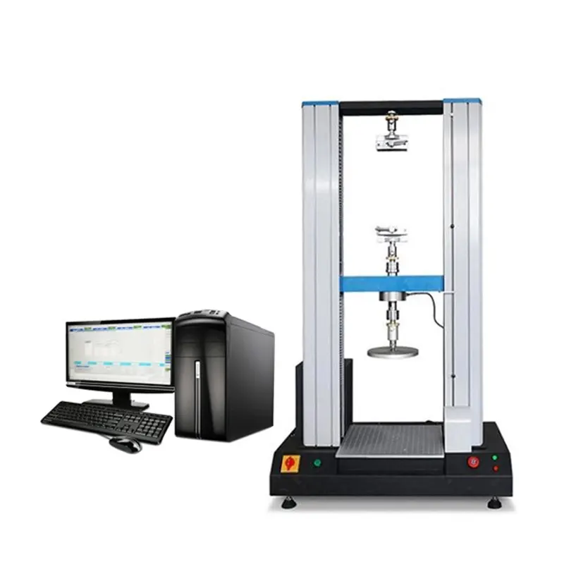
Universal Testing Machine
Measures static tensile yield strength, elongation at break, and slow flexural modulus—not high-strain dynamic rupture shock.
Melt Flow Indexer (MFI)
Characterizes polymer melt flow and molecular weight distribution in molten state—essential companion for resin QC.
Control the 6 Major Sources of Invalid Impact Data
Notch Cutter Tip Wear
Blunt cutter blades tear polymers instead of clean cutting, introducing micro-cracks or excessive fillet radius that distorts fracture energy.
Specimen Placement Misalignment
If the notch is not centered exactly midway between anvil supports, eccentric striking induces torsion and skews measured kJ/m² results.
Machine Base Instability
Impact reaction forces cause frame vibration if the tester is not bolted to a heavy, rigid bench; kinetic energy dissipates into the table.
Uncompensated Tare Losses
Ignoring aerodynamic windage of the pendulum hammer and axle bearing friction leads to systematic overestimation of plastic toughness.
Specimen Jamming & Tossing
Broken specimen halves that jam against the anvil or machine frame absorb secondary energy, producing falsely inflated peak readings.
Temperature Gradient Fluctuations
Testing samples directly out of conditioned storage without rapid transfer (<10 seconds) permits ambient thermal drift, especially below 0°C.
Build a Verifiable DR-C303 RFQ
Specify your polymer grades, sample dimensions, and applicable standards to receive an engineered proposal complete with pendulum sets and sample preparation tooling.
Polymers & Standards
- Target resin (PP, PE, ABS, PA, PC, Composites)
- Standard: ISO 179-1, ASTM D6110, or GB/T 1043
- Testing mode: Edgewise (1eA/1eU) vs. Flatwise
- Testing temperature: Ambient (23°C) or Low-temp (-40°C)
Pendulum & Strikers
- Required energy levels: 0.5J, 1J, 2J, 4J, 5J, 7.5J, 15J, 50J
- Striker tip radius: 2.0 mm (ISO) or 0.8 mm (ASTM)
- Electromagnetic automatic pendulum release
- Dual Charpy + Izod combo configuration requirement
Specimen Prep Accessories
- Motorized dedicated specimen notch milling machine
- Notch depth optical verification comparator
- Low-temperature thermal conditioning chamber
- Standard specimen injection mold cavity dies
Data Integration & Safety
- Color touchscreen display with micro-printer
- PC software for batch statistical curve analysis
- Interlocked full-surround acrylic safety enclosure
- Factory calibration certificate & ISO 17025 verification
DR-C303 Charpy Impact Tester FAQs
01What is the difference between Charpy and Izod impact testing?
02Why is absorbed energy required to fall within 10% to 80% of capacity?
03Can the DR-C303 test both notched and unnotched specimens?
04How does the tester correct for frictional and windage energy losses?
05Is a motorized notch cutter machine mandatory?
06What details are needed to receive a tailored DR-C303 quotation?
Configure your pendulum impact system: standard (ISO/ASTM) + energy set + striker nose + notch cutter.