
Benchtop Tensile Tester Selection Guide
Date: September 7, 2026 Categories: Buying Guides、Resources Views: 6766
Benchtop Tensile Tester Selection Guide
A benchtop tensile tester is selected as a complete test system—not by frame capacity alone. Begin with the specimen and current test method, then verify working force, usable test space, travel, grips, strain measurement, software and force verification across the range you will actually use.
Start with the test—not a “5 kN” or “10 kN” label
The same nominal frame capacity can produce very different systems once the load cell, grips, extensometer, available test space and software procedure are configured. A machine sized only for the largest predicted break force may be poorly matched to low-force films or fibers. A compact frame selected only by footprint may lack the usable grip separation or extension travel required by an elastomer.
Define the decision the result must support: incoming inspection, formulation comparison, production release, component validation or research. Then identify the current authorized procedure and record its specimen, conditioning, speed or strain-rate requirements, calculations and validity criteria. For example, ASTM D638 covers defined plastic specimens, while ASTM D882 is intended for thin plastic sheeting below the thickness limit stated in its scope; ASTM D412 addresses vulcanized rubber and thermoplastic elastomers. Similar test names do not make these procedures interchangeable.
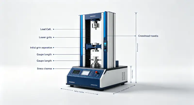
Seven decisions that define a benchtop tensile testing system
Define the specimen and current method
Provide material type, specimen drawing, thickness, width, overall length, gauge section, surface condition, preparation, conditioning and expected failure behavior. Confirm the method owner and current revision before translating it into machine requirements.
Estimate force, then define the working range
For a uniform tensile section, an initial estimate is force = expected tensile stress × original cross-sectional area. Treat this as a sizing input, not a substitute for prior test data. Include a justified overload margin, but also state the lowest force that must be measured so the supplier can review the load cell and verified range.
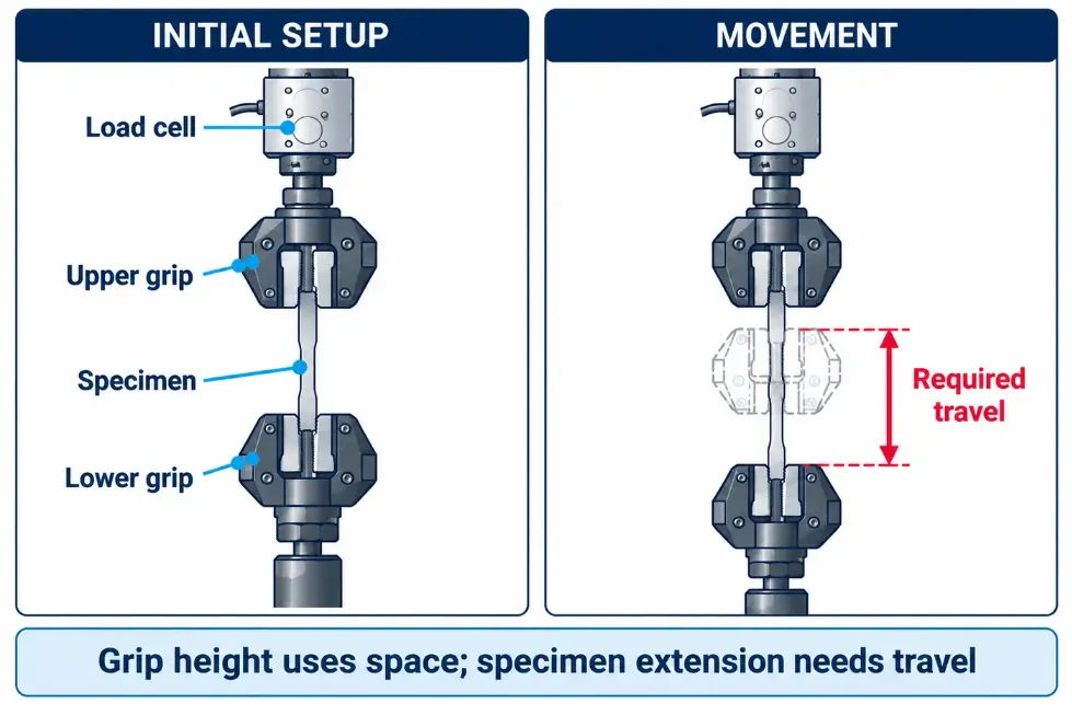
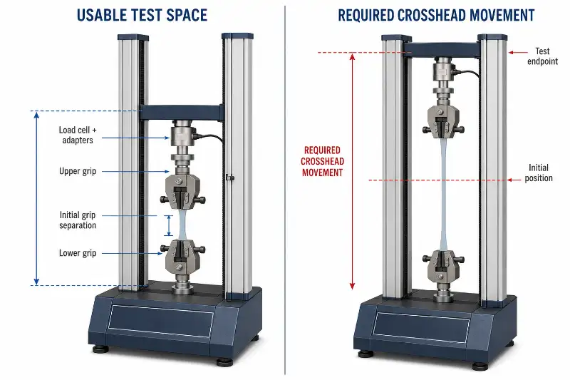
Calculate usable test space separately from travel
Usable vertical space must accommodate the load cell and adapters, both grips, initial jaw separation, specimen installation and protective clearance. Required movement depends mainly on the change in grip separation needed to reach the endpoint, plus setup and control allowance. Ask for drawings showing both available daylight and crosshead travel with the proposed load train installed.
Choose single-column or dual-column by the complete load case
Single-column systems can offer convenient side access for suitable low-force specimens. Dual-column benchtop frames can provide a wider load envelope and more symmetrical structure for higher forces or larger fixtures. Do not assign a universal capacity threshold: compare the documented frame range, stiffness, alignment, test space and accessory dimensions of the actual models.
Match the load cell and strain measurement to the result
Force capacity alone does not define useful measurement performance. Confirm accuracy and verification across the forces that matter. Crosshead displacement includes load-frame and grip-system effects; when the procedure or reported property requires specimen strain, select a suitable contact or non-contact extensometer with the necessary gauge length, accuracy and travel.
Select grips from geometry, surface and failure behavior
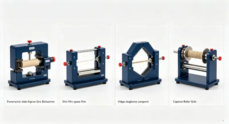
Specify jaw faces, clamping action, rated load, alignment and pneumatic utilities where applicable. Review whether the specimen slips, pulls out, breaks at the grip edge or is damaged by jaw pressure during trial testing. Cords, films, elastomers, rigid coupons and components may require fundamentally different load introduction.
Verify software, safety, records and lifecycle support
Check control modes, preload, limits, break detection, calculations, raw-data access, report templates, user permissions and export format. Also document guarding, emergency stop, fixture-change risk, calibration access, training, spare parts and service responsibilities for the destination country.
Single-column or dual-column benchtop frame?
| Decision factor | Single-column benchtop | Dual-column benchtop |
|---|---|---|
| Typical selection reason | Compact footprint and open access for a suitable low-force load train | Greater frame envelope or stiffness for higher loads, wider specimens or larger fixtures |
| Access | Side access can simplify loading some films, wires, textiles and small components | Working width is bounded by the columns; verify specimen and fixture clearance |
| Alignment and stiffness | Must be assessed for the actual force, grip offset and result sensitivity | Symmetrical architecture can be advantageous, but actual alignment and compliance still require verification |
| Test space | Check available daylight after all adapters and grips are installed | Check both vertical daylight and clear width between columns |
| Best decision rule | Select from the current model drawings, documented performance and proposed load train—not from generic capacity ranges. | |
How to prevent clearance and travel errors
Ask the supplier to complete a configuration drawing using the actual accessories. The drawing should show the load cell and adapter stack, upper and lower grip body heights, initial jaw separation, maximum separation, crosshead limits and specimen installation clearance. For a high-extension specimen, record the initial gauge or jaw separation and expected extension at the method endpoint; do not assume that nominal frame height equals usable travel.
| Input | What to provide | What it controls |
|---|---|---|
| Initial specimen setup | Overall length, gripping length and initial jaw separation | Minimum usable test space and installation access |
| Expected extension | Expected strain or extension at break/endpoint, with the calculation basis | Required separation change and extensometer travel |
| Load train | Load cell, adapters, grips, swivels and environmental accessories | Space consumed before the specimen is installed |
| Safety allowance | Overtravel, stop condition and clearance required by the configuration | Prevents limit contact and protects sensors/fixtures |
Match grips and extensometry to the specimen
| Specimen or test | Grip/fixture questions | Measurement questions |
|---|---|---|
| Rigid plastic dogbone | Jaw face, alignment, gripping pressure and grip-break tendency | Is direct strain required for modulus, yield or Poisson-related results? |
| Thin film or flexible sheet | Slip, tearing, jaw width, pressure consistency and low-force sensitivity | Gauge-mark, grip-separation or extensometer method permitted by the procedure |
| Rubber or elastomer | Specimen thinning, grip follow-up, long travel and break detection | Required gauge length and high-extension contact/non-contact range |
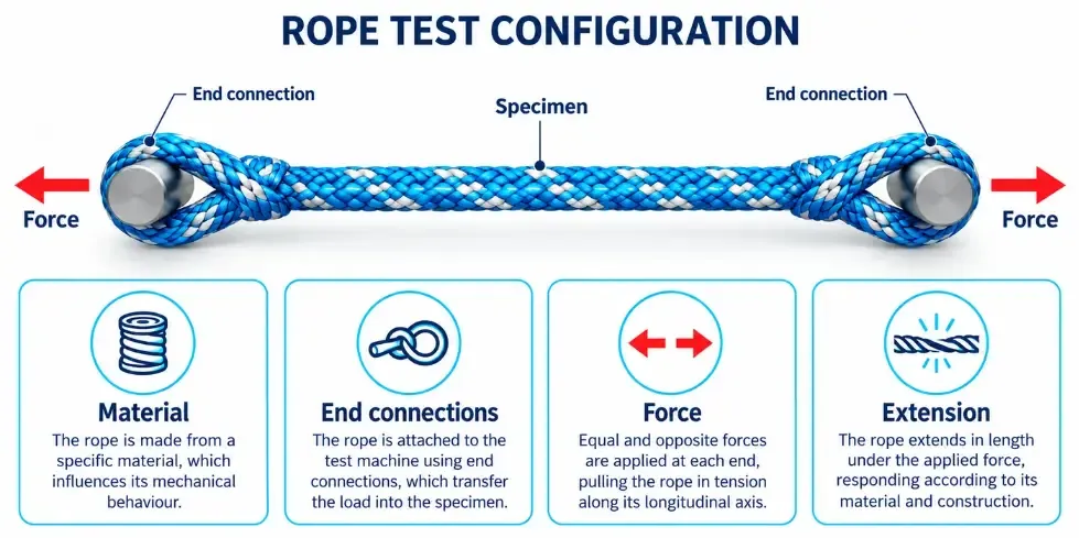
| Fiber, yarn, cord or wire | Stress concentration, capstan/roller path, bending radius and slippage | Force range, elongation reference and valid failure location |
| Peel or bonded assembly | Peel angle, moving fixture, backing stiffness and component adapter | Force averaging, travel, data rate and failure-mode recording |
Run representative specimens before final acceptance whenever possible. A successful trial should demonstrate stable gripping, suitable failure location, adequate measurement range and repeatable execution of the intended procedure—not simply that the machine can pull the sample apart.
Standards and verification: ask the right question
Application standards define how particular specimens are prepared, loaded, measured and reported. ASTM D638 and ISO 527 address tensile properties of plastics under defined conditions; ASTM D882 covers thin plastic sheeting; ASTM D412 covers vulcanized rubber and thermoplastic elastomers. The applicable material or product specification may add requirements or take precedence, so always confirm the current authorized documents.
Machine verification is a separate subject. ASTM E4 covers force verification practices for static or quasi-static testing machines, while ISO 7500-1 specifies calibration and verification of force-measuring systems for static uniaxial tension/compression machines. Ask which force ranges and indicators are included, what classification or acceptance criteria apply, who performs the work and what traceable documentation will be supplied. If strain results are required, address extensometer calibration/verification separately.
Where to continue your equipment review
Compare compact systems
Review current models, then verify every specification against your proposed load train.
Review the wider UTM range
Compare benchtop, floor-standing and hydraulic pathways by force and application.
Plastic and rubber applications
Review material-specific properties before assuming one universal configuration.
Textile and flexible specimens
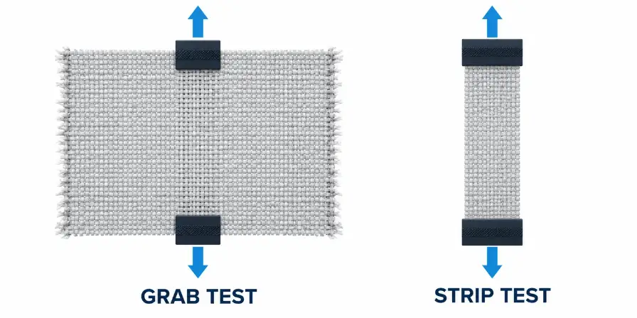
Consider grip pressure, slippage, gauge length and fabric-specific methods.
Benchtop tensile tester quotation checklist
| Field | Information to send |
|---|---|
| Test objective | QC, R&D, comparison, release or component validation; required results and units |
| Method | Organization, procedure number, current revision and customer deviations |
| Specimen | Material, drawing, dimensions, gripping section, preparation, conditioning and photos |
| Force | Expected minimum, typical and maximum working forces plus predicted break force |
| Movement | Initial separation, expected extension, endpoint and available test-space requirement |
| Load train | Grip type, jaw face, fixture, adapters, extensometer and environmental accessories |
| Workflow | Samples per batch/shift, changeover, operator skill and pneumatic/electrical utilities |
| Data and service | Calculations, raw data, reports, export, verification, training and destination country |
Turn your specimen and method into a test-system requirement
Send your current procedure, specimen drawing, expected force and extension, required results, daily workload and destination country. DERUI can review the frame, load cell, test space, grips, extensometry and software questions that must be resolved before quotation.
Benchtop Tensile Tester FAQs
Is a benchtop tensile tester the same as a universal testing machine?
A benchtop tensile tester can be a compact universal testing machine when its frame, controller and interchangeable fixtures support tension and other suitable static tests. “Universal” does not mean every method is supported; capacity, space, fixtures, measurement and software still have to match each procedure.
How much force capacity should I select?
Estimate the highest expected test and break forces from prior data or stress multiplied by original cross-sectional area, then apply a justified margin. Also state the lowest force that must be measured. The supplier should review the frame and load cell performance over the complete working range.
How do I know whether the tester has enough travel?
Provide initial grip separation, expected specimen extension and the test endpoint. Separately account for the space consumed by the load cell, adapters and grips. Request a configuration drawing showing usable daylight and crosshead travel with the actual accessories installed.
When is an extensometer required?
Use the measurement device required by the governing method and reported property. Crosshead displacement includes system compliance and grip effects, so direct specimen strain measurement may be necessary for modulus, yield or other strain-sensitive results.
What information is needed for a reliable quotation?
Send the current method, specimen drawing and material, expected force and extension, required calculations, grip or fixture needs, sample throughput, data format, utilities and destination country. This is more useful than requesting only a nominal kN capacity.