

How to Select a Tensile Testing Machine for PP Ropes
Date: October 21, 2026 Categories: Buying Guides、Resources Views: 6544
Start with the Rope Assembly You Need to Test
A PP rope tensile testing machine must be specified around the complete specimen, including its end connections. Nominal rope diameter and maximum machine force are not enough to decide whether the test can be performed.
Begin with the result you need: breaking force, a specified proof-load sequence, or elongation under a defined procedure. Then describe the rope, termination and space required to reach that result. This guide turns those questions into a practical configuration request.
Define the Rope and the Required Result
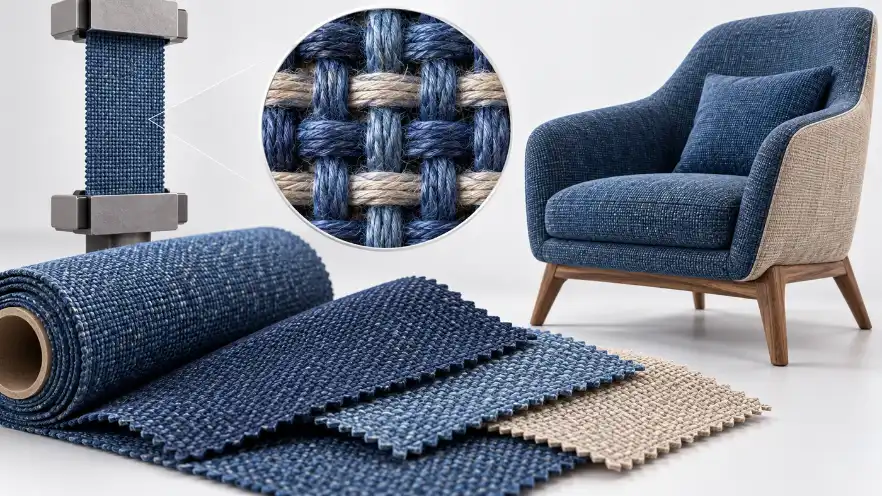
Identify polypropylene material, strand construction, nominal diameter, relevant product specification and the intended assembly. A test on a finished eye-spliced assembly may answer a different question from a test intended to characterize the rope body.
State whether the task is production comparison, customer acceptance, development or an assembly proof test. The objective affects preparation, test endpoint and the observations that belong in the report.
| Rope identity | Material, construction, diameter, batch and product specification |
|---|---|
| Assembly identity | Eye splice, socket or other termination, with dimensions and drawings |
| Required output | Breaking force, proof-load observations or method-defined elongation |
| Procedure | Authorized method, edition and customer amendments |
ISO 2307 addresses physical and mechanical properties of fibre ropes, including breaking force and elongation. The public abstract establishes the subject; use the authorized procedure for actual specimen preparation and testing.
Select Force from the Test, Not Diameter Alone
Use prior reports, a rope specification or a justified engineering estimate to define the expected force. Include the lowest force that must be measured, normal working values and the highest test endpoint. Distinguish proof load from predicted breaking force.
A requested 1,000 kN frame does not establish that every connection is rated for the same force. The sensor, pins, couplings, fixtures and attachment structure are all part of the load path. Ask for a configuration schedule rather than comparing only the largest number on the quotation.
There is no universal rope-diameter-to-machine-capacity conversion. Construction, material and termination change the required review. If force is unknown, send the product specification and mark the value as unknown rather than inventing one.
Review Eye Splices and End Connections
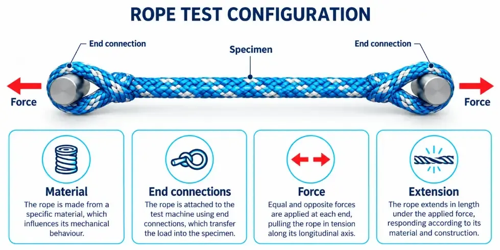
For an eye-spliced sample, provide the eye opening, splice construction, connection-centre distance and proposed pin or bearing geometry. Include how the sample will be installed and removed after loading.
Ask how the geometry introduces force and whether the attachment arrangement represents the required procedure. A supplier should not simply substitute a convenient pin or a sharp-edged contact and assume the result remains representative.
The diagram is a selection aid, not a rated fixture design. Final connection dimensions and ratings require the actual rope and test specification.
Calculate Space Separately from Travel
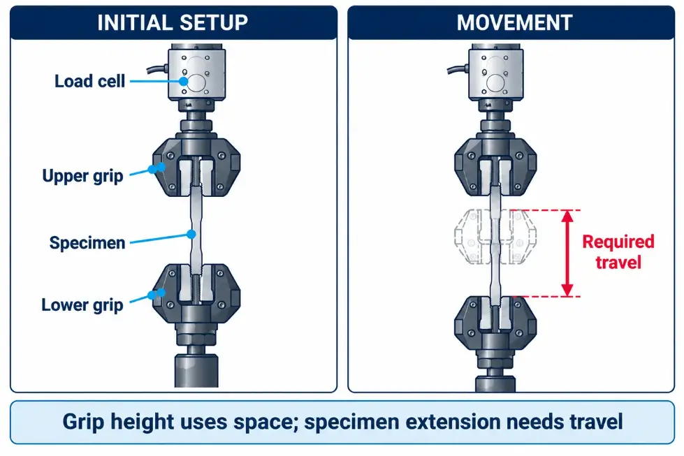
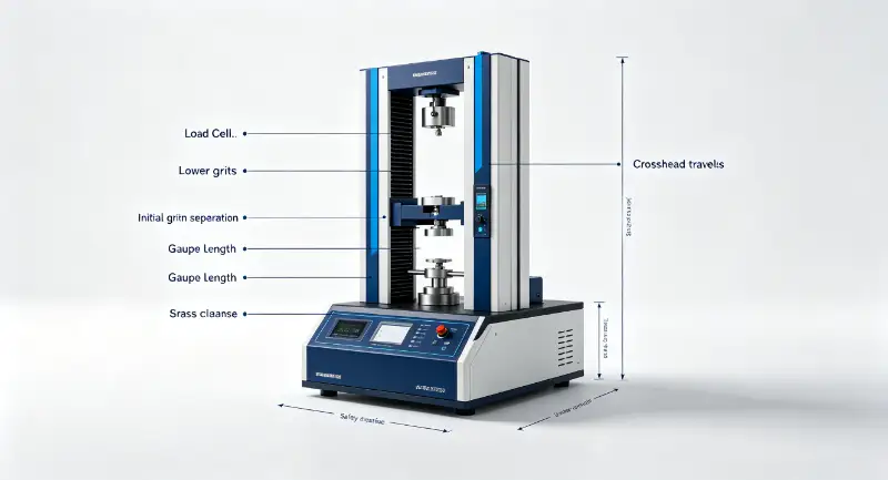
Mounted specimen length defines how much space the assembly occupies initially. Travel defines how far the loading system must move. Fixture seating, construction take-up and the expected extension all affect the required movement.
For a high-extension specimen, a long bed with insufficient actuator movement can still stop before the required endpoint. Conversely, a long-stroke actuator does not establish that the initial assembly will fit. Request a layout that shows both limits with the proposed attachments installed.
Define elongation measurement separately from actuator position. Rope seating and connection movement can contribute to machine displacement. If the report requires elongation over a defined reference length, specify the appropriate measurement arrangement.
Agree the Demonstration and Acceptance Scope
Where representative testing is available, agree what it needs to establish: mounting, usable movement, load measurement, endpoint control, observations and the report. A video of an unrelated rope does not validate your assembly.
Review rupture containment, operating access and the installation requirements for the actual stored-energy hazard. Obtain the proposed footprint, foundation loads, utilities, handling clearances and service access. These are project inputs, not a generic claim that horizontal machines are automatically safe.
The quotation should distinguish supplied hardware, options, customer responsibilities and acceptance records. Confirm the method and measurement scope before treating a calibration certificate as evidence that the whole procedure is covered.
Prepare a Useful Enquiry
Start with a rope photograph or drawing and the test objective. If known, add construction, diameter, expected force, mounted length, anticipated extension and the method. It is acceptable to identify missing inputs for discussion.
For equipment review, see DERUI horizontal tensile testing equipment. The product page describes the equipment route; this guide explains the project information needed to select it.
Send Your Rope Test Requirement
Ask for a proposed load path, space/travel review and quotation scope. A clear specimen description is more useful than requesting a price for a force rating alone.