

Configure the Right 50–300 kN Universal Testing Machine
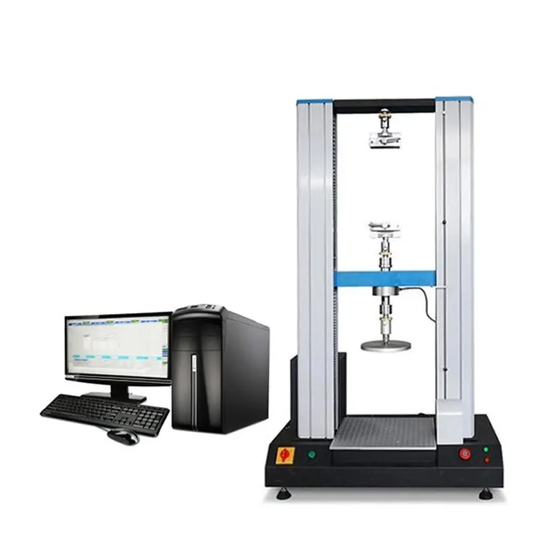
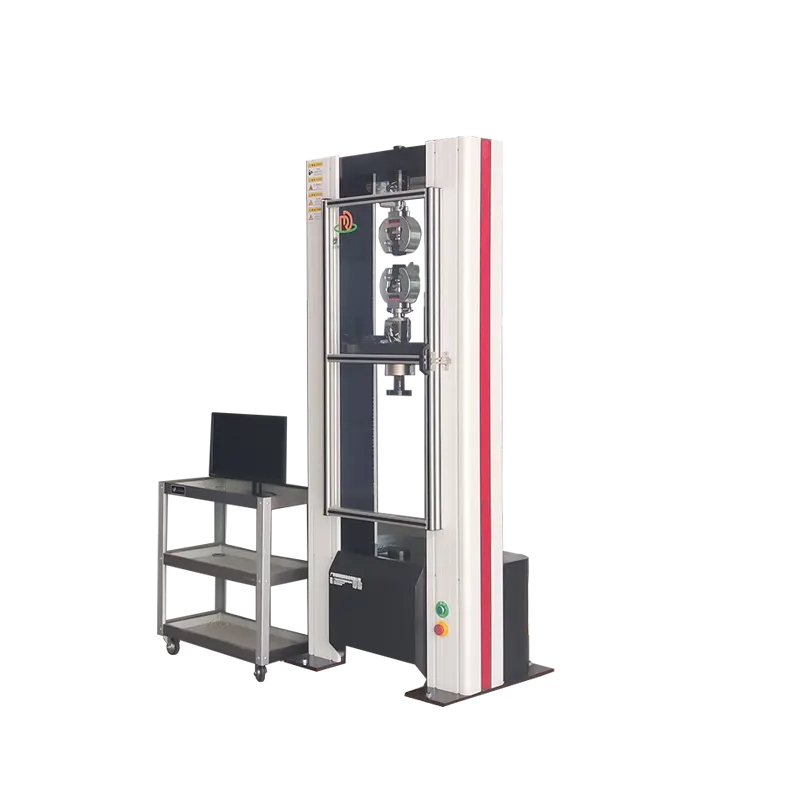
Select a floor-standing dual-column system for static tensile, compression and flexure testing by matching the method, specimen, working load and complete measurement chain—not by maximum frame capacity alone.
Compare 50, 100, 200 and 300 kN Frames
The nominal capacity establishes the frame limit. The correct system also depends on the usable force range, fixture weight, specimen dimensions, required travel and measurement devices.
Moderate-force testing
Consider for test programs whose verified working loads remain comfortably inside a 50 kN frame envelope.
Confirm: lowest required force, grip mass, travel, specimen strength and overload margin.
Broader laboratory range
Consider when higher-strength specimens, larger fixtures or additional working-load margin exceed a 50 kN configuration.
Confirm: floor or table format, test-space geometry, fixture handling and site access.
Higher-force components
Consider for larger specimens and proof or materials tests requiring a substantially higher static load envelope.
Confirm: force train, alignment, guarding, electrical supply and installation conditions.
Upper family capacity
Consider when the documented method and expected peak load justify the highest nominal capacity in this product family.
Confirm: low-force measurement need, fixture mass, usable space, floor loading and service access.
A larger frame does not automatically produce a better result.
Force capacity, load-cell range, resolution, alignment, grips, extensometry, software calculations and the test procedure work as one measurement chain. A 300 kN frame should not be selected only as “future capacity” when the normal test load is much lower.
Choose Capacity from the Working Load
Define what must be measured before choosing what the machine can withstand.
Define the specimen and method
Provide material, geometry, preparation, loading mode, current procedure and required reported properties.
Estimate normal and peak force
Separate the usual measurement range from occasional peak or proof loads and include the fixture contribution.
Confirm usable measurement range
Match each force range to an appropriate load cell and its verified range; nominal frame capacity is not the low-force accuracy specification.
Check physical test space
Confirm daylight, travel, column spacing, grip length, specimen elongation and room for chambers or large fixtures.
Specify strain measurement
State whether crosshead displacement is sufficient or the method requires a contact, automatic or non-contact extensometer.
Verify the complete procedure
Review speed or strain-rate control, calculations, acceptance rules, data output, guarding and operator workflow.
The Frame Is Only One Part of the Test System
Reliable results require compatible hardware, measurement devices and method-defined software—not a load frame sold in isolation.
Load and specimen interface
Load cells: select capacity and verified measurement range for each work envelope.
Grips and fixtures: match material, geometry, surface, force and failure mode.
Test space: allow for grips, specimen, elongation, fixtures and optional chambers.
Measurement and control
Extensometry: choose gauge length, strain range and contact method from the procedure.
Control: confirm the required loading or strain-rate functions for the selected system.
Software: define calculations, report fields, permissions, export and traceability needs.
Avoid Four Common UTM Specification Errors
A frame can have enough maximum force and still be the wrong measurement system. Review these risks before a model is approved.
Choosing only by maximum force
A high-capacity frame does not establish the lowest force that can be measured with the required uncertainty. Define normal and peak working loads separately.
Ignoring the installed fixture envelope
Grips, adapters, platens and extensometers consume usable height and width. Confirm the complete installed geometry, not empty-frame daylight alone.
Treating crosshead travel as specimen strain
Frame, grip and load-train compliance contribute to crosshead movement. Use the strain-measurement device required by the method and reported property.
Assuming every method is included
A universal frame does not automatically include every grip, fixture, calculation or verification. Confirm the complete supply scope method by method.
Configure for the Actual Test Procedure
A suitably configured system can support static tension, compression, flexure and proof-load work. Compatibility must be checked against the current method edition, specimen and required result.
| Test mode | Typical configuration questions | Example method families to review |
|---|---|---|
| Tensile | Specimen geometry, gripping surface, working force, elongation and strain measurement | Metallic materials: ASTM E8/E8M or ISO 6892-1; plastics: ASTM D638 or ISO 527 |
| Compression | Platen size, parallelism, stability, deflection or strain measurement and guarding | Confirm the material- or component-specific compression procedure |
| Flexure | Three- or four-point fixture, support span, deflection measurement and usable test width | Plastics: ASTM D790 or ISO 178; other materials require their applicable procedure |
| Proof load / component | Custom fixture, load path, hold sequence, acceptance criteria and safe containment | Confirm the product, customer or industry-specific procedure |
Standards are configuration references, not a blanket compliance claim. Confirm the current edition, required accessories, calibration or verification scope and laboratory procedure before ordering.
When Is an Electromechanical Dual-Column UTM the Right Choice?
Choose this family for
Method-controlled static or quasi-static tensile, compression and flexure tests within the confirmed force, speed, travel and measurement capabilities of the configured system.
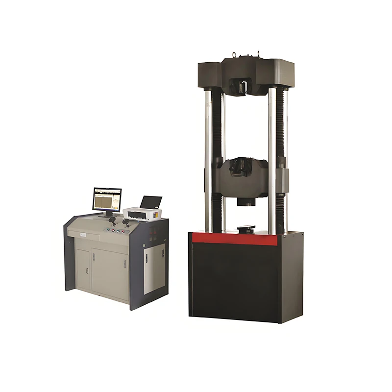
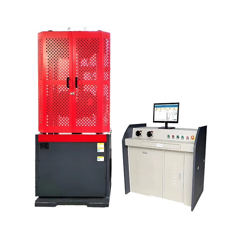
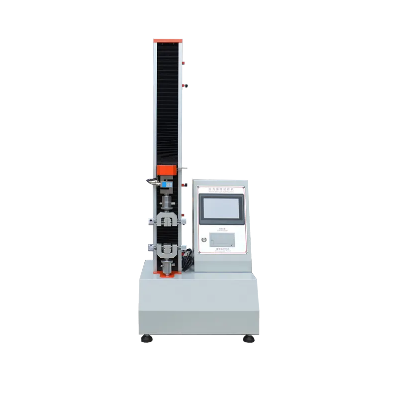
It is the logical step above a compact benchtop tensile tester when capacity, stiffness or usable test space requires a floor-standing dual-column frame.
Review another platform when
The program requires substantially higher force, hydraulic actuation, specialized high-force fixtures or operating conditions outside this electromechanical family.
Compare the dedicated hydraulic testing machine range and confirm dynamic or fatigue requirements separately.
What the Final Technical Offer Should Confirm
Use the final quotation and model datasheet—not a generic family description—as the controlling specification for the purchased system.
| Item to confirm | Why it matters | Required evidence |
|---|---|---|
| Nominal frame capacity and usable force range | Separates structural limit from the force range required for results | Model datasheet and proposed load-cell range |
| Speed, travel and installed test space | Determines whether the complete specimen and fixture setup can execute the method | Configuration drawing with grips or fixtures installed |
| Force and strain verification scope | Defines which measurement ranges and devices are covered | Applicable verification plan, certificate scope and referenced procedure |
| Standard and optional supply | Prevents missing grips, adapters, extensometers, guards or software functions | Itemized commercial and technical offer |
| Site, power and commissioning requirements | Prevents delivery or installation delays | Installation drawing, utility list and agreed service scope |
Confirm the Site and Supply Scope Before Ordering
A complete quotation should define both the machine configuration and the conditions needed to install, verify and use it.
Delivery route
Door, elevator, corridor, lifting and unpacking clearances.
Operating space
Ceiling height, service clearance, fixture handling and environmental limits.
Floor conditions
Machine mass, floor loading, levelling and anchoring requirements if applicable.
Power and services
Destination voltage, frequency, phases and any pneumatic or other utility needs.
Risk controls
Guarding, debris containment, travel limits, emergency stop and local requirements.
Documentation
Verification scope, reports, manuals, training, commissioning and agreed acceptance checks.
50–300 kN Dual-Column UTM FAQ
How do I choose between 50, 100, 200 and 300 kN?
Start with the documented working and peak forces, then check load-cell range, fixture mass, overload margin, test space and the governing method. Select the smallest configuration that safely covers the complete procedure and any justified future work.
Does a 300 kN frame provide better accuracy for low-force tests?
Not automatically. Low-force performance depends on the selected load cell, its verified range, the complete measurement chain and the method. Tell DERUI the lowest and highest forces that must be measured.
Can one frame use more than one load cell?
A multi-load-cell configuration may be possible, but compatibility, mounting, protection, calibration or verification and software setup must be confirmed for the proposed system.
Can the same machine perform tension, compression and flexure tests?
A universal frame can support these static test modes when equipped with the correct grips or fixtures, sensors, test space and software method. Each procedure should be reviewed individually.
When should I choose electromechanical rather than hydraulic?
This family targets configurable static or quasi-static testing with an electromechanical drive. Consider a hydraulic platform when the required force, actuator behavior, fixtures or application falls outside the confirmed capability of this family.
Is an extensometer required?
It depends on the property and procedure. Crosshead movement is not a substitute for specimen strain when the method requires local strain measurement. Provide the material, gauge length, strain range and target result.
What installation information is required?
Provide the destination, power supply, access route, floor and ceiling constraints, operating environment, available utilities, safety requirements and space for operators, fixtures and service.
What should I send to receive an accurate quotation?
Send the method and edition, specimen drawing or photos, expected force range, required travel and speed, grips or fixtures, strain measurement, tests per day, reporting needs, destination and power. Price, lead time and final supply scope can then be confirmed for the actual configuration.
Send the Test Method and Specimen Before Choosing a Frame
DERUI can review the working force, test space, grips, extensometer, software and site requirements as one system before preparing a configuration and quotation.