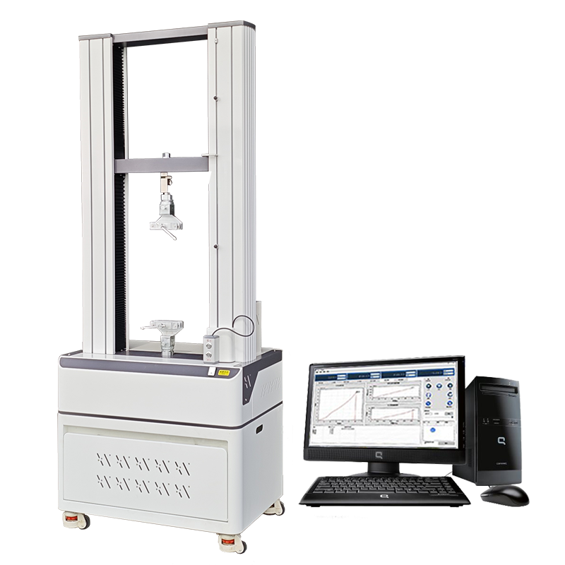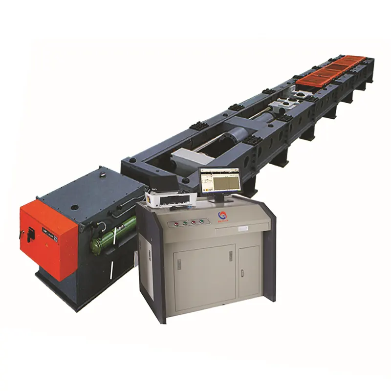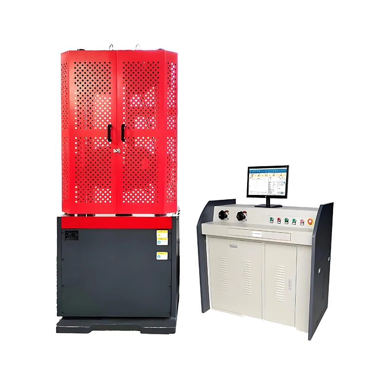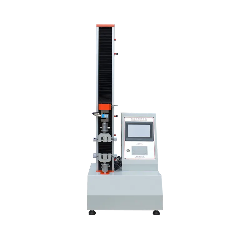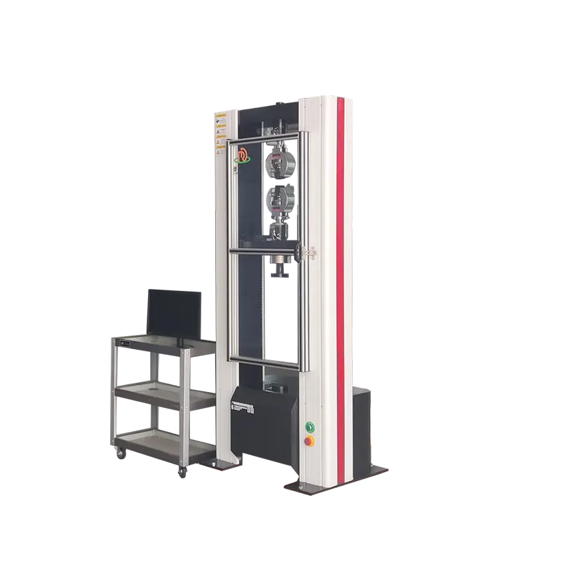


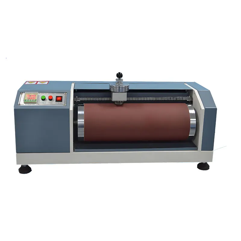
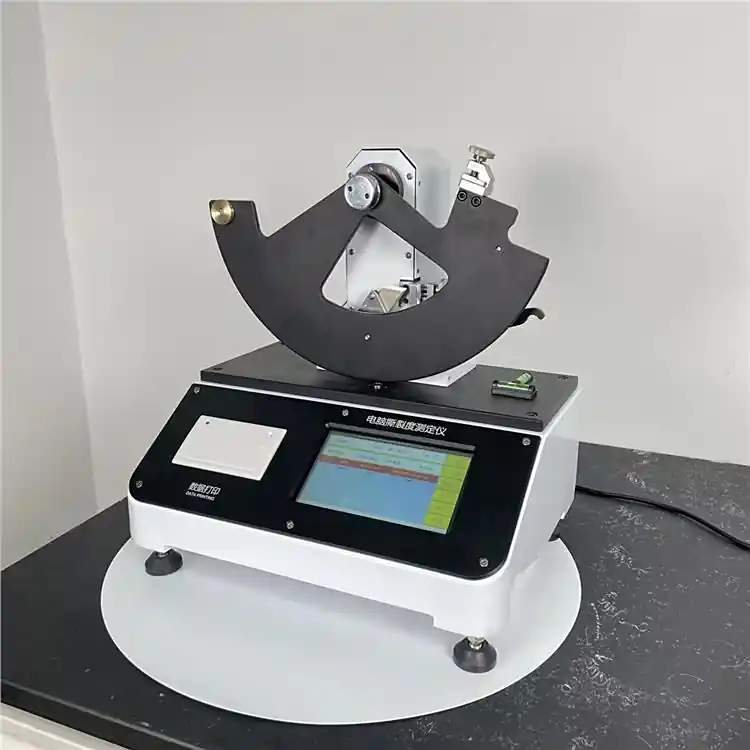
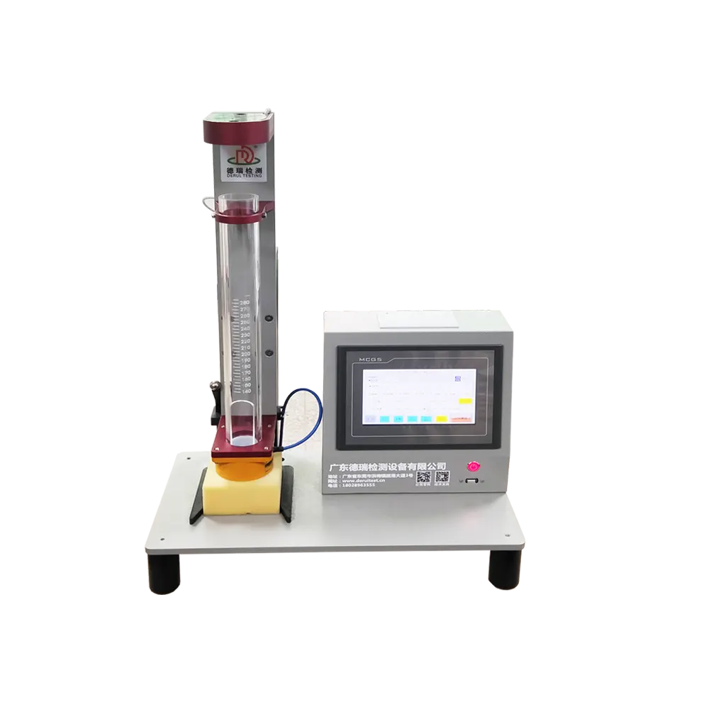
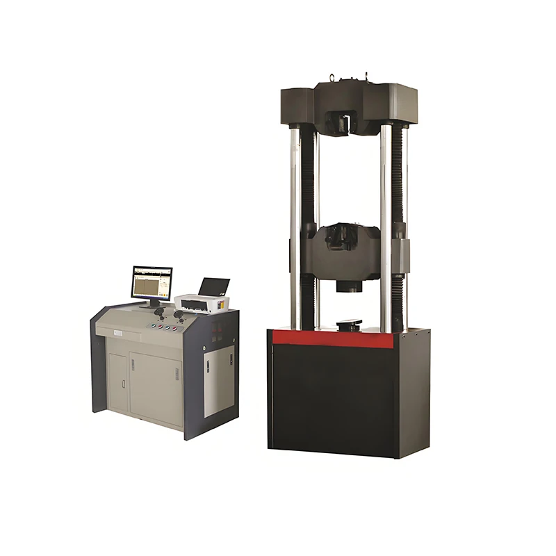


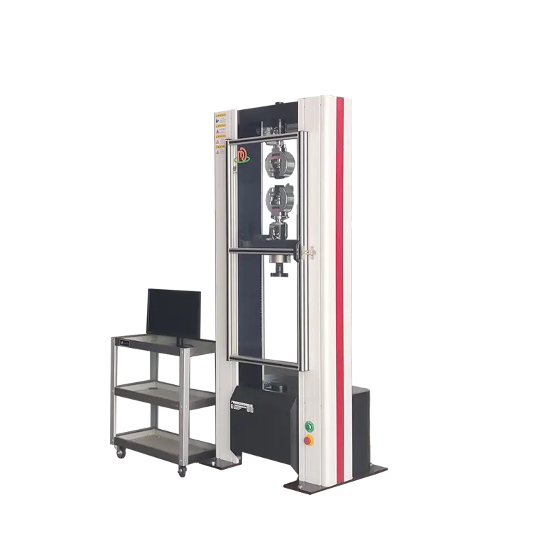
DR-L202-2 Universal Testing Machine
The DR-L202-2 is a computer-controlled, dual-column universal testing machine intended for compatible tensile, compression, flexure or shear procedures when the correct load cell, grips or fixtures, test space, speed and measurement devices are configured.
Quick answer: this is not one fixed “all-material” package. Select it only after the specimen, current method, expected working and peak forces, required travel, strain or deflection result and reporting workflow have been defined.
DR-L202-2 in the DERUI UTM Range
This page serves users evaluating a medium-force dual-column platform. The related pages retain separate search intent, preventing the same generic “universal tester” content from competing across the site.
DR-L202-2
Assess the published 500–2000 kg configurations, 1000 mm stroke and complete test setup.
Material-strength category
Use when the correct equipment family or loading architecture is not yet known.
Compact benchtop systems
Use for lower-force tests where bench footprint and lighter fixtures are priorities.
Higher-force floor systems
Use when the required load, specimen or fixture envelope exceeds this configuration.
Configure More Than the Test Frame
A rigid frame does not by itself produce tensile strength, yield or elongation. The method-specific measurement chain determines whether the requested result can be generated and defended.
1 · Force measurement
Choose the load cell around normal working force and expected peak—not capacity alone. Confirm range, overload protection and verification scope.
2 · Specimen holding
Match grip type, jaw face, opening, clamping method and rated load to the specimen so slip or jaw breaks do not distort results.
3 · Strain or deflection
Crosshead movement is not automatically specimen strain. Confirm whether the method requires an extensometer or another direct measurement device.
4 · Procedure and report
Define preload, speed or rate control, endpoints, calculations, units, curve output, raw-data export and report fields.
AI-ready definition: a universal testing machine is a configurable test platform. Its valid application is determined by the combined frame, load cell, grips or fixtures, travel, control mode, strain or displacement measurement, software method and verification status.
Potential Test Pathways and Required Configuration
These pathways show what must be confirmed; they are not blanket compliance claims for the base machine.
| Test pathway | Typical configuration questions | Result questions |
|---|---|---|
| Tensile | Specimen geometry, wedge/pneumatic/special grips, jaw faces, gauge length, required travel and break containment. | Peak or break force, tensile strength, yield, modulus and elongation; identify which need direct strain measurement. |
| Compression | Platen diameter, parallelism, specimen height, seating/preload and remaining vertical space. | Force at displacement, compression strength, stiffness, deformation or cyclic response. |
| Flexure | Support span, roller diameter, specimen dimensions, loading nose and deflection measurement. | Flexural force, strength, modulus or deflection at a defined event. |
| Shear / component force | Purpose-built fixture, load direction, alignment, interfaces, guarding and rated load. | Peak, separation, insertion/extraction or force-displacement behaviour defined by the procedure. |
Do not select by material name alone. Two specimens made from the same material may require different grips, load cells, travel, speed, strain measurement and calculations.
Check Usable Test Space Before Ordering
The published maximum stroke is 1000 mm excluding fixtures. The installed load train consumes space, and long grips or fixtures can materially reduce the movement available to the specimen.
Send a specimen drawing plus the proposed fixture heights. This is more reliable than comparing stroke numbers from catalogues.
A Practical UTM Test Workflow
This workflow helps laboratories separate machine operation from method validity and makes technical discussions more useful before purchase.
Define
Confirm specimen, procedure revision, conditioning and required reported properties.
Configure
Select verified force range, fixtures, test envelope and strain/deflection device.
Prepare
Measure the specimen, inspect contact surfaces, set gauge length and method fields.
Run
Align, preload if required, monitor slip or abnormal failure and preserve raw data.
Review
Check failure location, curve quality, calculation inputs, units and report traceability.
Grip slip · jaw break · off-axis loading · overload · unexpected noise · incomplete data.
Machine/load cell ID · fixture · method revision · specimen dimensions · operator · date · raw curve.
Eight Inputs for a DR-L202-2 Technical Review
Send these together so force range, fixtures, travel, measurement and documentation can be evaluated as one system.
Material and product
Construction, surface, flexibility and expected failure behaviour.
Current method
Standard or internal procedure, revision and any customer-specific conditions.
Specimen drawing
Thickness, width/diameter, overall length, gripping sections and gauge length.
Force range
Typical working force, peak/break force and any low-force stages.
Movement and rate
Required travel, speed/rate control, preload and endpoint.
Holding and alignment
Grip/fixture preference, jaw opening, contact surface and alignment needs.
Required results
Force, strength, yield, strain, modulus, deflection, curve and report fields.
Site and workflow
Throughput, power, installation access, operator language and documents.
Fastest review: attach the method and specimen drawing, then list expected force, movement and required results.
DR-L202-2 Universal Testing Machine FAQs
01What capacities are currently published for DR-L202-2?
02Can the same setup test every material?
03Does crosshead travel equal specimen elongation?
04Is DR-L202-2 automatically ASTM or ISO compliant?
05What does 1000 mm maximum stroke mean?
06What should be sent for a quotation?
Configure the Test—Not Only the Frame
Send the specimen, method, force range, movement and required results for a technical review.