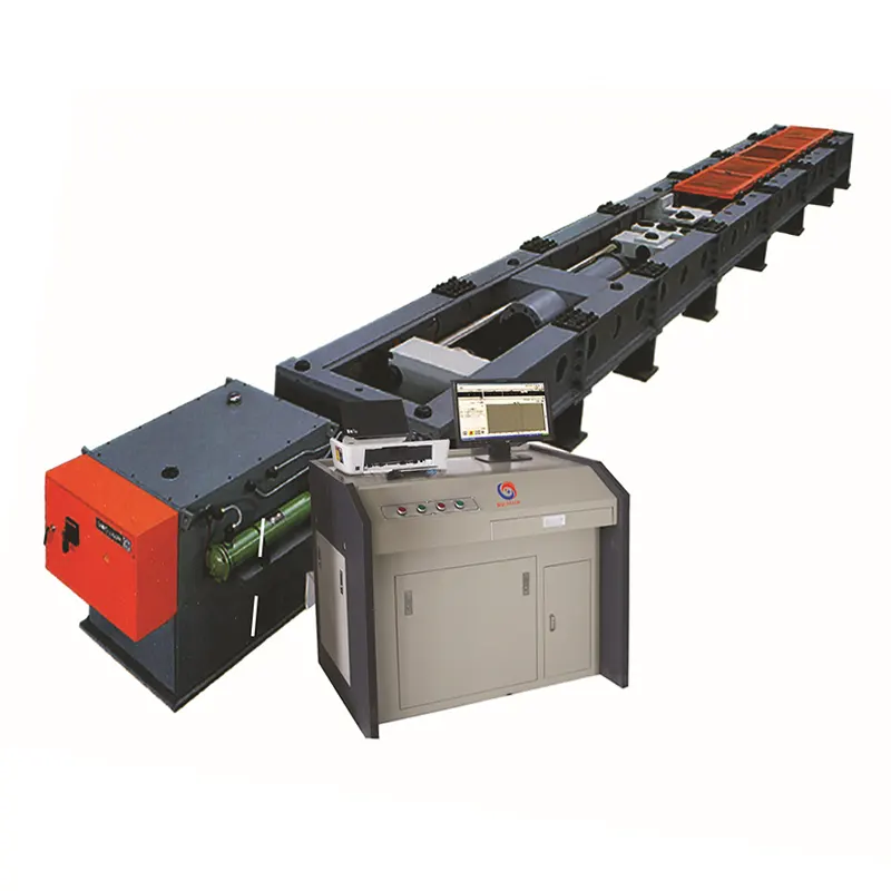
Material testing equipment configured for your test method and specimen.

DERUI manufactures material testing equipment for quality control and R&D.
WhatsApp Consultation:+86 135 2795 8363

Tensile, compression, flexure and shear test systems

Material Strength Testing Equipment& Universal Testing Machines

Choose a benchtop, floor-standing electromechanical or hydraulic system around the test method—not force capacity alone. The right configuration depends on the specimen, expected working load, test space, fixtures and the result you need to measure.

Derui supplies configurable systems for static tensile, compression, flexure, shear and peel applications. Method capability and conformity must be confirmed against the selected machine, accessories and current test standard before ordering.

01

Compact electromechanical systems

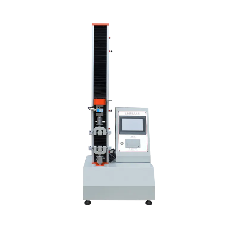
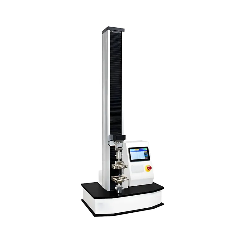
Benchtop Universal Testing Machines

Compare compact systems for suitable tensile, compression, flexure, peel and component tests. Select by the specimen, expected working and break loads, usable test space, travel, grips and required force or strain measurement—not footprint alone.

Force rangeTest spaceGrips & fixturesStrain measurement
CONFIRM BEFORE SELECTION
Applicable fabric method, specimen type and dimensions
Expected breaking force, elongation and gauge length
Grip faces, clamping pressure and slip prevention
Confirm Before Selection
Required peel method, angle and specimen width
Test speed, backing support and preparation procedure
Expected peel-force range and reported result
Confirm Before Selection
Rubber type, specimen geometry and test method
Expected break force, elongation and required travel
Grip faces and contact or non-contact strain measurement
Confirm Before Selection
Test mode, specimen material and dimensions
Routine working load, peak load and test speed
Usable test space, fixtures and measurement channels
02

Dual-column electromechanical systems

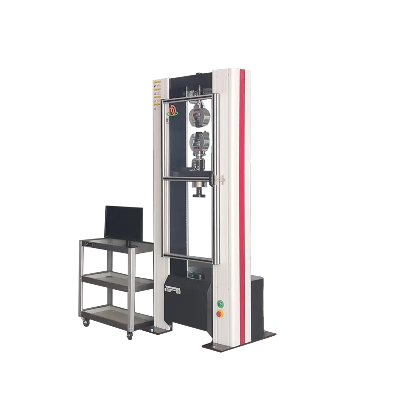
Floor-Standing Universal Testing Machines

Compare floor-standing systems when the specimen, working load, fixture mass or required travel exceeds a benchtop setup. Confirm usable test space, load-cell range, grips, alignment and strain or deflection measurement before selecting the frame.

Working loadTest envelopeLoad-train alignmentStrain or deflection
CONFIRM BEFORE SELECTION
Required tensile, compression or flexure procedures
Working-force range, specimen size and test space
Load cell, fixtures, extensometer and reporting workflow
CONFIRM BEFORE SELECTION
Material, specimen geometry and governing tensile method
Required strength, yield and elongation results
Force range, grip type and strain-measurement method
Confirm Before Selection
Required loading modes and governing procedures
Specimen dimensions, working force and required travel
Grips, fixtures, sensors and report requirements
03

High-force hydraulic systems

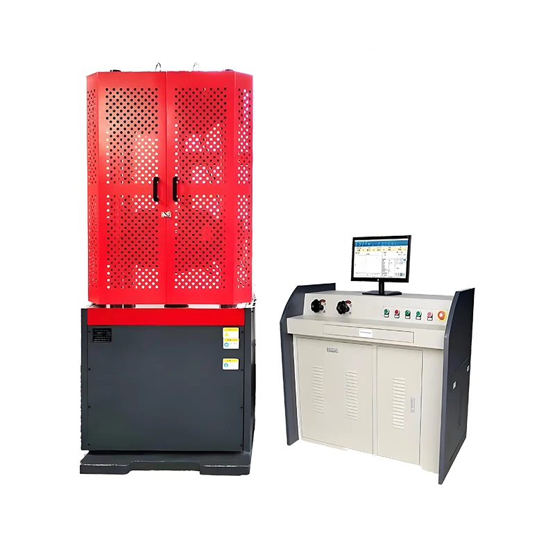
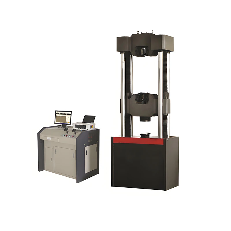
Hydraulic Universal Testing Machines

Compare hydraulic systems for high-force testing of metals, construction materials, fasteners, large components and long specimens. Confirm the loading mode, working range, test space, grips, utilities, floor loading and installation access before selecting a configuration.

Working rangeLoading modeUtilitiesInstallation access
Confirm Before Selection
Required loading modes and verified peak force
Specimen dimensions, test space and handling method
Fixtures, floor loading, utilities and installation access
Confirm Before Selection
Test method, loading mode and working-force range
Specimen geometry and required strain measurement
Grips, control functions, utilities and verification scope
Confirm Before Selection
Specimen length, end connections and loading layout
Working force, required stroke and gripping interfaces
Floor space, foundation, handling and installation access

Configuration support

Why Work With Derui on a Configured Test System?

A useful proposal must define more than the load frame. Derui can review the test requirement and identify the machine, fixtures, measurement channels, site inputs and project scope that require confirmation before ordering.

01

Application review

Start With the Specimen and Method

Provide the material or component, geometry, current procedure, expected working and peak loads, required result and test frequency. These inputs establish the configuration question before a frame is selected.
02

System definition

Review the Complete Measurement Chain

Match the frame and force-measurement range with the grips or fixtures, available test space, strain or deflection measurement, control sequence, software outputs and required safety limits.

03

Scope confirmation

Define What the Quotation Includes

Confirm selected options, interfaces, verification and documentation requirements, report fields, power or hydraulic services, installation conditions and acceptance items in the final commercial scope.

04

Delivery planning

Agree on Site and Support Requirements

State the destination country, voltage, access route and operating environment. Confirm packing, installation, training, spare parts, calibration or remote-support requirements as quoted options rather than assumed inclusions.

Important: Final capability, method suitability, documentation and service scope depend on the selected machine and confirmed quotation.

Need Help Selecting a Material Testing System?

Send the material or specimen, test standard, required result and expected force range. We’ll help narrow the frame, grips and measurement options for your application.

Send Your Test Requirements →

Testing fundamentals

Material Strength Testing& How a UTM Works

Material strength testing measures how a prepared specimen responds to a controlled load. A universal testing machine can perform selected tensile, compression, flexure, shear or peel methods when its frame, load cell, fixtures, travel, speed and strain-measurement system match the procedure.

01 · PULLING LOAD

Tensile Testing

Evaluates properties under tension, such as tensile strength, yield behaviour and elongation where required. Examples include ASTM E8/E8M for metals and ISO 527 for plastics.

02 · PUSHING LOAD

Compression Testing

Evaluates response under compressive loading, including deformation, strength or stiffness as defined by the method. Examples include ASTM E9 for metals and ISO 604 for plastics.

03 · BENDING LOAD

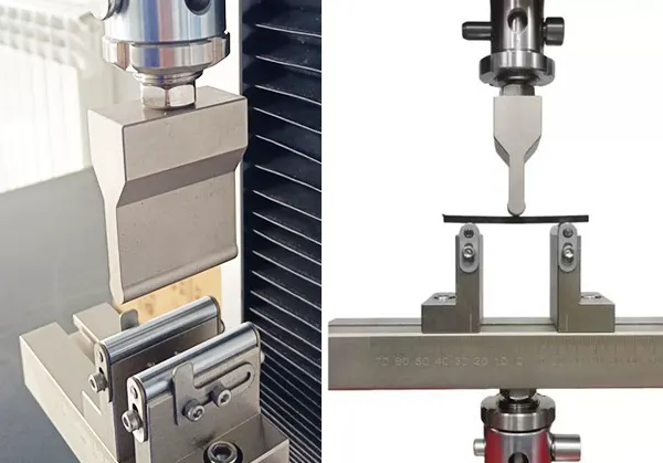
Flexure Testing

Measures bending response using a defined support span and loading arrangement. ASTM D790 and ISO 178 are common examples for plastics and related materials.

04 · INTERFACE LOAD

Shear and Peel Testing

Assesses joints, laminates or adhesive bonds with method-specific fixtures. ASTM D1002 addresses single-lap adhesive shear, while ASTM D903 covers peel or stripping strength.

A Typical UTM Test Workflow

1

Define the methodConfirm the material, specimen, current standard and results to report.

2

Prepare and mountPrepare the specimen and install the specified grips, platens or fixture.

3

Configure and loadSet the method parameters, safety limits and measurement channels, then run the test.

4

Review and reportCheck the curve and calculated results before approving or exporting the report.

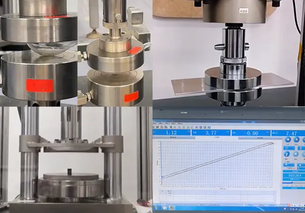
Compression testing setup with platens and test software

Compression test planning

Match the Compression Test to the Specimen and Method

Compression testing measures how a specimen responds to a controlled pushing load. Depending on the material and procedure, the required result may include compressive strength, deformation, stiffness, modulus or behaviour at a specified load.

The test setup must be defined before selecting the machine. ASTM E9 is used for compression testing of metallic materials under specified conditions, while ISO 604 covers compressive properties of plastics. Always confirm the applicable standard and current edition for the specimen being tested.

Specimen and methodMaterial, geometry, preparation and governing procedure
Force and travelExpected working load, deformation and usable test space
Platens and alignmentContact faces, fixture geometry and axial load application
Measurement and reportingForce, displacement or strain channels and required calculations

From test result to engineering evidence

Turn Material Strength Data into Better Decisions

A strength value is useful only when the specimen, procedure and measurement conditions are known. Well-defined tensile, compression and flexure results help engineering and quality teams compare materials, validate components and investigate changes in production.

01 · MATERIAL SELECTION

Compare Candidate Materials

Use results generated under the same method and conditions to compare strength, stiffness, deformation or failure behaviour relevant to the application.

02 · PRODUCT VALIDATION

Check Components and Designs

Apply the specified loading mode and acceptance criteria to determine whether a specimen or component meets the defined design or verification requirement.

03 · QUALITY CONTROL

Monitor Process Consistency

Compare production results against an approved specification or baseline and investigate meaningful changes in material, processing or assembly.

Decision-ready data

Control the Measurement Chain

Method: current procedure, loading mode and test rate

Specimen: geometry, preparation and conditioning

System: suitable frame, load cell, grips and alignment

Report: units, calculations, traceability and acceptance criteria

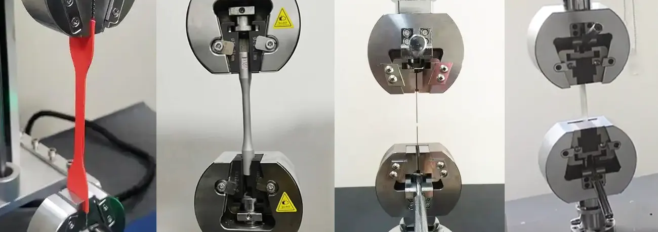
Tensile testing specimens held in different grips
Three-point and four-point flexure test fixtures

Flexure test planning

Define the Bend Setup Before Selecting the System

Flexure testing measures how a specimen responds to bending. The governing method defines the specimen dimensions, support span, loading arrangement, test rate and results to report. ASTM D790 and ISO 178 are common examples for plastics; other materials and products may require different procedures.

3-point bendingOne loading nose applies force between two supports, concentrating the maximum bending moment near the centre.
4-point bendingTwo loading noses create a region of approximately uniform bending moment between the loading points.

Confirm Before Configuration

Material, specimen geometry and current test method

Support span, roller and loading-nose geometry

Expected force, travel and test speed

Deflection or strain measurement and reporting needs

Common Grips and Fixtures for Universal Testing Machines

The fixture is part of the measurement chain. Match it to the test method, specimen geometry, expected force, machine interface and required result.

Wedge Grip

For tensile testing of flat or round specimens where suitable jaw faces and clamping action are needed to resist slip.

Configured by
Application
Confirm specimen shape, dimensions, surface, expected force and required jaw face before selection.

Pneumatic Grip

Air-actuated gripping for repeated tests that benefit from consistent clamping and faster specimen changes.

Air Supply
Required
Confirm specimen material, gripping area, force range, jaw faces, air pressure and actuation requirements.

Threaded Grip

Positive axial attachment for specimens or adapters with compatible threaded ends.

Thread Match
Required
Confirm thread size and pitch, end geometry, working force, adapter interface and load-train alignment.

Shear Fixture

A method-specific fixture for applying defined shear loading to joints, fasteners, laminates or material sections.

Method-Specific
Fixture
Confirm the governing method, specimen or assembly geometry, load direction, force range and machine interface.
Seven Checks Before Selecting a Material Testing System

Evaluate the proposed system against the actual method, specimen, working range, measurement and laboratory workflow—not a general list of features. Record each requirement before comparing configurations or quotations.

  • Test Scope
  • Force & Tooling
  • Measurement
  • Safety & Usability
  • Software & Data
  • Automation
  • Support & Supply

Start with the tests the laboratory must perform. A machine is suitable only when the complete configured system supports the specimen, method and required result.

Methods
List each tensile, compression, flexure, shear or peel procedure.
Specimens
Record material, geometry, dimensions, preparation and conditioning.
Results
Define the properties, curves and acceptance criteria to report.
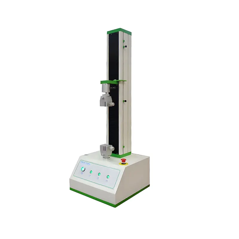
DR-L201 Desktop tensile testing machine

DR-L201 Desktop tensile testing machine

The DR-L201 desktop tensile testing machine is a compact, cost-effective benchtop solution for precise tensile, compression, and flexure tests. Fully compliant with ASTM and ISO standards, it delivers reliable performance for quality control, educational labs, and R&D on low to medium-force materials like polymers, textiles, and thin metals.

Material Strength Testing Equipment FAQs

Answers to common questions about UTM selection, test methods, force capacity, fixtures, extensometers, verification and installation. Confirm the final configuration against the current method and actual specimen.

What is material strength testing, and what can a UTM measure?

Material strength testing applies a controlled load to a prepared specimen and records how it responds. The result depends on the selected method and the complete measurement chain—not the machine name alone.

01
TEST MODE

Match the Loading Mode to the Test Objective

Define whether the specimen will be pulled, compressed, bent, sheared or peeled and identify the current procedure.

02
MEASURED RESULT

Specify the Property That Must Be Reported

State whether the report requires strength, yield behaviour, elongation, modulus, deformation or load at a defined event.

03
SYSTEM CONFIGURATION

Configure the Complete Measurement Chain

Confirm the frame, load cell, grips or fixtures, travel, test speed and strain or displacement measurement needed for that result.

What should be defined before selecting a UTM?

Send the material, specimen dimensions, applicable method, expected force range and every result that must appear in the report.

Send Your Test Requirement →

Can one universal testing machine test metals, plastics and composites?

One universal testing machine may support metals, plastics and composites, but the same unchanged setup will not suit every material or method.

01
APPLICATION RANGE

List Every Material and Procedure

Identify the specimen type, dimensions, loading mode and test standard for each planned application.

02
CHANGEABLE HARDWARE

Match Load Cells, Grips and Fixtures

Different materials may require different force ranges, jaw faces, fixtures, travel and strain-measurement devices.

03
SHARED PLATFORM

Verify the Common Frame Envelope

Confirm that one frame provides the working load, usable test space, speed and travel required by all included methods.

What should be compared across materials?

Provide a method-and-specimen list so each required load cell, fixture, extensometer and software function can be identified in the supply scope.

Review a Multi-Material Setup →

How do I choose between a benchtop, floor-standing and hydraulic testing machine?

Choose the frame from the specimen, working load, loading mode and usable test space. Benchtop, floor-standing and hydraulic systems serve different test envelopes.

01
BENCHTOP SYSTEM

Use a Compact Frame When the Test Fits

Consider a benchtop system when the required force, travel, grips and specimen can be accommodated within its working envelope.

02
FLOOR-STANDING SYSTEM

Allow More Space for Larger Setups

Consider a floor-standing electromechanical frame for higher loads, larger fixtures, longer specimens or greater travel.

03
HYDRAULIC SYSTEM

Review High-Force Testing Requirements

Consider a hydraulic system for defined high-force or large-component work after confirming loading mode, utilities, floor loading and access.

What should you send for a frame recommendation?

Send specimen dimensions, routine and peak loads, installed fixture height, required travel, loading mode and destination site conditions.

Request a Frame Recommendation →

How much force capacity does my universal testing machine need?

Select capacity from the lowest force that must be measured through the highest routine or expected peak force. Maximum frame rating alone is not a selection method.

01
WORKING RANGE

Define Routine and Peak Forces

Provide the normal test load, estimated break or peak load and any preload or abnormal event that must be considered.

02
LOW-FORCE RESULT

Protect the Lowest Reportable Measurement

Confirm which load cell and verified working range cover the lowest force that must appear in the report.

03
COMPLETE SYSTEM

Review Capacity with Space and Tooling

Evaluate load-cell range, frame stiffness, fixture weight, test space and travel as one configuration.

What force information is needed?

Send the lowest reportable force, normal working range, estimated peak or break load and the methods used to estimate them.

Review Your Force Range →

Does a universal testing machine automatically comply with ASTM or ISO standards?

A universal testing machine does not automatically make a test ASTM- or ISO-compliant. Compliance depends on the current method, the configured apparatus and how the test is performed.

01
CURRENT METHOD

Identify the Exact Standard and Edition

Confirm the full method number, material scope and current edition instead of citing ASTM or ISO in general.

02
APPARATUS

Check Every Method Requirement

Review specimen preparation, dimensions, fixtures, loading rate, measurement devices, calculations and reporting requirements.

03
VERIFICATION

Separate Test Method from Machine Verification

Define required force, displacement or strain verification and request the applicable evidence for the supplied system.

What should be confirmed in writing?

List the exact method, required results, included apparatus, verification documents and any items that remain the laboratory’s responsibility.

Review a Standards-Based Setup →

When is an extensometer needed for material testing?

Use an extensometer when the method or required result depends on strain measured over a defined gauge length rather than crosshead movement alone.

01
REQUIRED RESULT

Confirm Why Strain Must Be Measured

Identify modulus, yield, elongation or another strain-based result required by the applicable procedure.

02
SPECIMEN

Match the Device to the Test Piece

Provide material, geometry, gauge length, gripping arrangement and available mounting space.

03
MEASUREMENT RANGE

Define Strain, Travel and Environment

Confirm expected strain, required travel, contact or non-contact preference and any temperature or chamber conditions.

What should you send for extensometer selection?

Send the method, specimen drawing, gauge length, expected strain range, required result and test environment.

Request an Extensometer Review →

How do I select the correct grips or fixtures for a UTM?

The correct grip or fixture must apply the intended load while holding or supporting the actual specimen without unacceptable slip, misalignment or invalid damage.

01
SPECIMEN INTERFACE

Define Shape, Size and Surface

Provide specimen drawings, dimensions, gripping section, surface condition and any fragile or compressible features.

02
LOADING REQUIREMENT

Match the Fixture to the Method

Confirm tensile, compression, flexure, shear or peel loading, expected force, alignment and contact requirements.

03
MACHINE FIT

Check Capacity, Space and Connection

Verify rated capacity, jaw opening, fixture mass, machine interface, installed height and remaining test travel.

When is a custom fixture review needed?

Send a drawing or representative specimen when standard jaws or supports cannot reproduce the required loading and alignment.

Review Your Grip or Fixture →

What documentation, training and support should be confirmed before ordering?

Documentation and support should be written into the quotation or supply agreement so both parties understand the delivery, acceptance and lifecycle responsibilities.

01
DOCUMENT PACKAGE

List Required Records

Define manuals, configuration records, software information, packing list and calibration or verification documents.

02
INSTALLATION AND ACCEPTANCE

Assign Responsibilities and Sign-Off

Agree who handles delivery, installation, commissioning, operator training, acceptance criteria and final approval.

03
LIFECYCLE SUPPORT

Confirm Support After Delivery

Record support channels, warranty scope, maintenance needs, spare and wear parts and the process for future reverification.

What should be agreed before the order?

Confirm the document list, service location, training scope, acceptance method, warranty boundary and responsible party for each delivery stage.

Define the Supply and Support Scope →

What site information is needed before installing a material testing system?

Site readiness should be reviewed before the final configuration is approved, especially for floor-standing and hydraulic systems.

01
DELIVERY ACCESS

Confirm the Route to the Test Area

Provide door, corridor and elevator dimensions, lifting restrictions and the final equipment position.

02
SPACE AND FLOOR

Check the Installation Envelope

Confirm ceiling height, operating and maintenance clearance, floor loading and any anchoring or foundation requirements.

03
UTILITIES AND ENVIRONMENT

Define Available Site Services

State voltage, frequency, phase, grounding, compressed air, hydraulic or cooling needs, temperature, humidity, dust and vibration conditions.

What site details should accompany the inquiry?

Send the destination country, available power, room and access dimensions, floor information and photos or drawings of the proposed installation area.

Request a Site Readiness Review →

What affects the price of a universal testing machine?

The price of a universal testing machine is determined by the complete usable configuration and delivery scope, not only the frame’s headline capacity.

01
CORE SYSTEM

Define Frame and Measurement Hardware

Confirm frame type, force capacity, load cells, controller and the required displacement or strain measurement.

02
TEST ACCESSORIES

List Every Included Test Setup

Identify grips, fixtures, extensometers, guards, environmental options and method-specific accessories.

03
DELIVERY SCOPE

Compare Commercial Boundaries

Check software, documentation, verification, packing, shipping, installation, training, warranty and excluded items.

How should quotations be compared?

Use one written requirement list and mark every component and service as included, optional or excluded in each quotation.

Request a Defined Quotation →

WhatsAppWhatsApp
WhatsApp
MessageMessage

Send Inquiry